
NAVAIR 01-1A-505-2
011 02
TO 00-25-255-1
Page 6
TM 1-1500-323-24-2
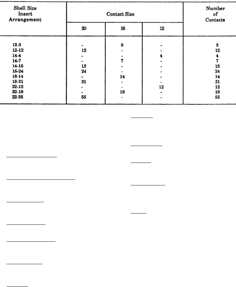
Table 2. Threaded Coupled Insert Arrangements
31. Peripheral. Seal. This seal is around the edge of pin
23. INSERTS. The non-resilient material used for all
insulator and designed so that when mating the
inserts shall be a high grade dielectric having electrical
connector, tension is put on seal and greatly reduces
and mechanical characteristics suitable for the purpose
compression set.
intended. The impact strength shall be such that
material shall not chip, crack, or break during assembly
32. Interfacial Seal. This seal is achieved by insulator
or normal maintenance.
faces meeting when plug and receptacle are mated.
24. Crimp Snap-In Contacts. Snap-in contacts designed
for NAS1662 or NAS1663 can be crimped with standard
33. Wire Seal. This seal is accomplished by a multiple
M22520/1 crimp tool.
ripple design exceeding wire sealing requirement of
NAS1599.
25. Closed-Entry Socket Contacts. These contacts
eliminate damage from abuse by test probes and help
34. Insert Retention. Insert retention is accomplished
to correct any misaligned pins during engagement.
by a hard plastic wafer firmly locked into a groove in
shell and a strong adhesive bond between insert and
26. Contact Insertion. Insertion is accomplished from
shell.
rear of connector. When contact is fully inserted, the
clip tines snap securely behind contact shoulders.
35. Keying. Keying is used in shell-enclosed connectors
to obtain polarization, which assures correct location
27. Contact Extraction. Extraction is accomplished with
when mating a connector.
use of a removal tool.
36. INSERT ARRANGEMENT. The insert arrangement
28. Contact Retaining Clip. The contact retaining clip
is number and size of contacts available by shell size
is completely encased in a tough plastic wafer to protect
(Table 2).
clip from damage.
37. I N S E R T C O N F I G U R A T I O N . T h e i n s e r t
29. Moisture Sealing. Complete sealing is achieved by
configuration is the manner in which contacts are
combining four seals, shell, peripheral, interfacial, and
placed within insert in a standard configuration. All
wire seal.
arrangements identified in Table 2 are illustrated
(Figure 4).
30. Shell Seal. This seal is effected when plug shell
pushes against sealing ring in receptacle when
connectors are mated.