
NAVAIR 01-1A-505-3
TO 1-1A-14-3
TM 1-1500-323-24-3
003 02
1 September 2011
Page 32
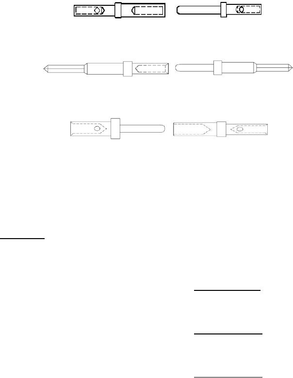
M39029/57-354
M39029/58-360
M39029/72-393
M39029/71-390
M39029/72-394
M39029/71-391
M39029/72-395
M39029/71-392
M39029/87-470
M39029/89-494
M39029/87-471
M39029/89-495
M39029/87-472
M39029/89-496
M39029/87-473
M39029/89-497
Figure 15. MIL-DTL-24308 Contacts
11. Dash Number. The dash number denotes the
arrangement (Figure 14) contained in the connector part
connector type and contacts.
number (Figures 1 thru 13), for each connector. Shell
size is equal to the second number in the insert
arrangement (Example: Insert arrangement "A-2-2" =
12. DESIGN AND CONSTRUCTION. Connectors
Shell size 2, Insert arrangement "A-5-1" = Shell size 5).
and accessories are designed and constructed to
withstand normal handling incidental to installation and
16. Connectors M24308/1. The M24308/1 connectors
maintenance.
are class G, general purpose receptacles with solder type
socket contacts. For the insert arrangements refer to
13. INSERTS. Inserts are molded or bonded one-piece
Figure 1.
construction, except for IDC. The inserts are so designed
that the inserts cannot be removed from shells. The
17. Connectors M24308/2. The M24308/2 connectors
contact retention system for removable crimp contact
are class G, general purpose receptacles with removable
connectors is a metal retention clip.
crimp type socket contacts. For insert arrangements refer
to Figure 2.
14. INTERCHANGEABILITY.
All
connectors
having the same military part number are completely
18. Connectors M24308/3. The M24308/3 connectors
interchangeable with respect to installation and
are class G, general Purpose plugs with solder type pin
performance. Solder and crimp contact connectors are
contacts. For the insert arrangements refer to Figure 3.
intermateable (Table 1 and Figures 1 thru 13).
15.
The
insert
INSERT
ARRANGEMENT.