
NAVAIR 01-1A-505-3
TO 1-1A-14-3
TM 1-1500-323-24-3
003 02
1 September 2011
Page 34
Contact Inspection Hole
Figure 16. Insulation Gap
34. CONTACT INSERTION. Insert wired or unwired
g. With firm even pressure, press tool against
contacts in accordance with following procedure:
contact shoulder and seat contact into cavity (Figure 18).
A slight click may be heard as retention tines snap into
a. Remove sealing plug and/or contact from contact
place behind contact shoulder.
cavity (Paragraph 38).
b. Ensure wire or cable on contact is routed through
Contact Shoulder
connector backshell.
c. Select correct insertion tool (Table 2).
Insertion Tool
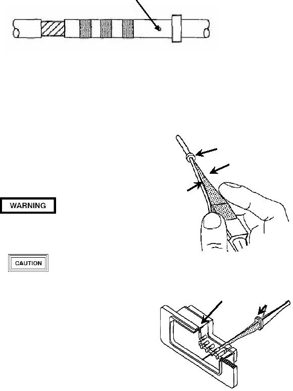
d. Insert wire into insertion tool (Figure 17).
Wire
Metal tool tips are sharp and can cause injury to
personnel and/or damage to connectors.
Figure 17. Inserting Contact into Insertion Tool
Present metal tooling in some instances has
Retaining Clip Insertion Tool
damaged the wire sealing grommet at the end of
the connectors. Plastic tools are preferred.
Caution should be exercised in the use of tooling.
Inspect tips of metal tools for distortion of probe
before use as connector damage can occur.
e. Insert tip of contact into cavity. Start contact
insertion near connector center cavities and work
outward.
f. Axially align contact with contact cavity.
Figure 18. Contact Insertion