
NAVAIR 01-1A-505-3
TO 1-1A-14-3
TM 1-1500-323-24-3
007 02
1 September 2011
Page 31/(32 Blank)
96. CONNECTOR REMOVAL AND
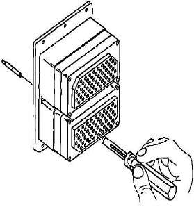
h. Push contact completely out of rear of
INSTALLATION. If connector is severely damaged
connector before disengaging removal tool (Figure 24).
or cannot be repaired using the above procedures,
proceed as follows:
a. Starting from outside of damaged connector,
tag wires and remove all contacts from connector
(paragraph 91). If contact cannot be removed, cut wire
as close to connector as possible and attach new
contact (paragraphs 85 and 86).
b. Starting from center of new connector, insert
contact into correct cavity (paragraph 87). Repeat
procedure until all contacts are installed in new
connector.
97. CONNECTOR BUILDUP SOLDER
CONTACTS.
98. For buildup procedures for solder contacts refer to
NAVAIR 0l-lA-505-1, WP 016 00.
99. CONNECTOR CLEANING AND
Figure 24. Broken Wire Contact Removal
PRESERVATION.
100.For connector cleaning and corrosion control
procedures refer to NAVAIR 01-lA-505-1, WP 026 00.