
NAVAIR 01-1A-505-3
TO 1-1A-14-3
TM 1-1500-323-24-3
010 02
1 September 2011
Page 21/(22 Blank)
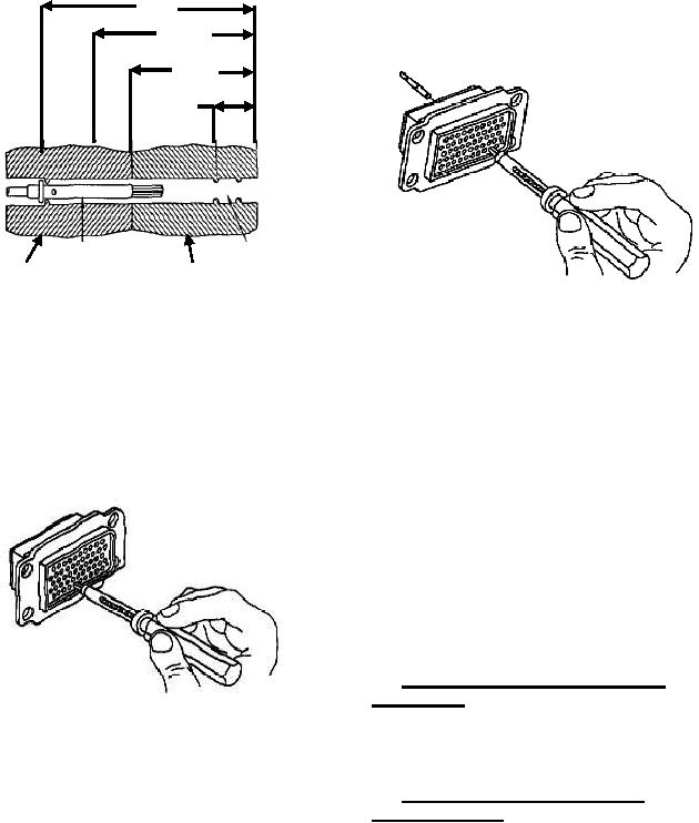
h. Push contact completely out of rear of
1/2
connector before disengaging removal tool (Figure
21).
3/8
5/16
1/8
Contact
Seal
Plastic
Resilient
Wire Barrel
Area
Retaining
Rear Insert
Insert
Figure 21. Broken Wire Contact Removal
Figure 19. Typical Connector Dimensions
d. If resistance is felt before removal tool
50. CONNECTOR REMOVAL AND
reaches back end of contact, withdraw tool slightly,
INSTALLATION. If the connector is severely
rotate about l/6 of a turn, and reinsert tool. Repeat
damaged or cannot be repaired using the above
rotating and insertion procedure until tool passes with
procedures, proceed as follows:
minimum additional force to 5/16 inch depth back
end of contact (Figure 20).
a. Starting from outside of damaged connector,
tag wires and remove all contacts from connector
(Paragraph 44). If contact cannot be removed, cut
wire as close to connector as possible and attach new
contact (Paragraphs 38 and 39).
b. Starting from center of new connector, insert
contact into correct cavity (Paragraph 40). Remove
tag from wire. Repeat procedure until all contacts are
installed in the new connector.
51. CONNECTOR BUILDUP, SOLDER
CONTACTS.
Figure 20. Unlocking Contact Retention
52. For buildup procedures of solder contacts, refer
Mechanism of Broken Wire Contact
to NAVAIR 01-lA-505-1, WP 016 00.
e. Wiggle removal tool gently to help it into
insert bore and over back of contact. Additional
53. CONNECTOR CLEANING AND
rotation may be required if broken strands are
PRESERVATION.
encountered.
54. For connector cleaning and corrosion control
procedures refer to NAVAIR 01-lA-505-1,
f. Continue insertion of removal tool until
WP 026 00.
positive stop is felt at about l/2 inch depth.
g. Exert axial pressure on engaging end of
contact, using appropriate pin or socket as pusher. If
contact does not move, seat removal tool more firmly.