
NAVAIR 01-1A-505-3
TO 1-1A-14-3
TM 1-1500-323-24-3
010 02
1 September 2011
Page 17
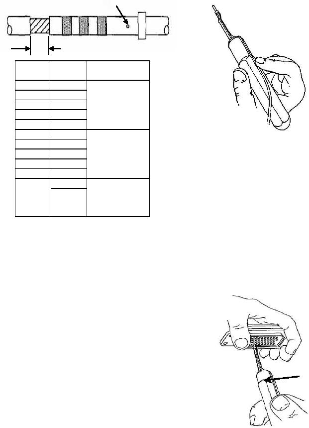
Contact Inspection Hole
Insulation Gap
Contact
Wire
Insulation
Size
AWG
Gap
22D
26
22M
1/32" Min.
22
24
1/16" Max.
22
20
20
16
20
Figure 10. Inserting Contact into Insertion Tool
18
1/32" Min.
16
5/64" Max.
12
14
f.
Axially align contact with contact cavity.
12
10
1/32" Min.
g. With firm even pressure, press tool against
Twice Dia.
contact shoulder and seat contact into cavity (Figure
8
Wire Insulation
8
11). A slight click may be heard as retention tines
Max
snap into place behind contact shoulder
h. Pull tool straight out of contact cavity.
Figure 9. Insulation Gap
Remove tool from wire. Pull back lightly on wire to
ensure contact is properly seated.
40. CONTACT INSERTION. Insert wired or
i. Seal connector as required (Paragraph 41)
unwired contacts in accordance with following
and install backshell.
procedure:
a. Remove sealing plug and/or contact from
contact cavity (Paragraph 44).
b. Ensure wire or cable on contact is routed
through connector backshell.
c.
Select correct insertion tool (Table 4 or 6).
d. Place wire and contact assembly into colored
Tool must be at
tip of insertion tool (Figure 10). Ensure tool tip is
right angle to
over conductor barrel and butted against contact
shoulder.
insert face.
e. Insert tip of contact into cavity. Start contact
insertion near connector center cavities and work
outward.
Figure 11. Contact Insertion