
NAVAIR 01-1A-505-3
TO 1-1A-14-3
TM 1-1500-323-24-3
010 02
1 September 2011
Page 16
39. CONTACT CRIMPING. Crimp contact in
36. CONNECTOR BUILDUP.
accordance with following procedure:
37. WIRE DIAMETER BUILDUP. If wire outside
diameter is not large enough to fill wire sealing
a.
Select correct crimp tool (Table 4 or 6).
grommet holes, buildup wire outside diameter by
applying heat-shrinkable insulating sleeving (SAE-
b. Perform die closure check, install positioner
AMS-I-23053). This must be accomplished prior to
and set selector knob for gage of wire.
contact insertion. The outer diameter shall be within
the applicable size range specified (Table 7).
c. Insert stripped wire into contact conductor
barrel. Ensure all wire strands are inside contact
38. WIRE STRIPPING. Strip wire in accordance
conductor barrel and visible in contact inspection hole
with following procedure:
(Figure 9).
a. Cut wire to proper length. Ensure enough
d. If insulation gap is too large, trim conductor
wire remains for adequate strain relief without
as required. If insulation gap is too small, trim
leaving excess slack.
insulation as required.
b. Strip insulation from end (NAVAIR 0l-lA-
e.
Crimp contact to wire.
505-1 WP 009). Select contact (Table 3 or 5).
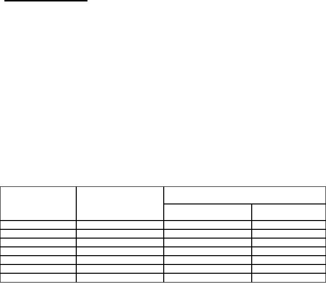
Table 7. Wires and Diameters
Wire Size
Finished Wire Outside Dimensions
Contact
(AWG)
Size
Minimum (Inches)
Maximum (Inches)
20
24
0.040
0.090
20
22
0.040
0.090
20
20
0.040
0.090
16
18
0.068
0.130
16
16
0.068
0.130
16
14
0.106
0.170
12 Shielded
12
0.106
0.170