
NAVAIR 01-1A-505-3
TO 1-1A-14-3
TM 1-1500-323-24-30
13 02
1 September 2011
Page 20
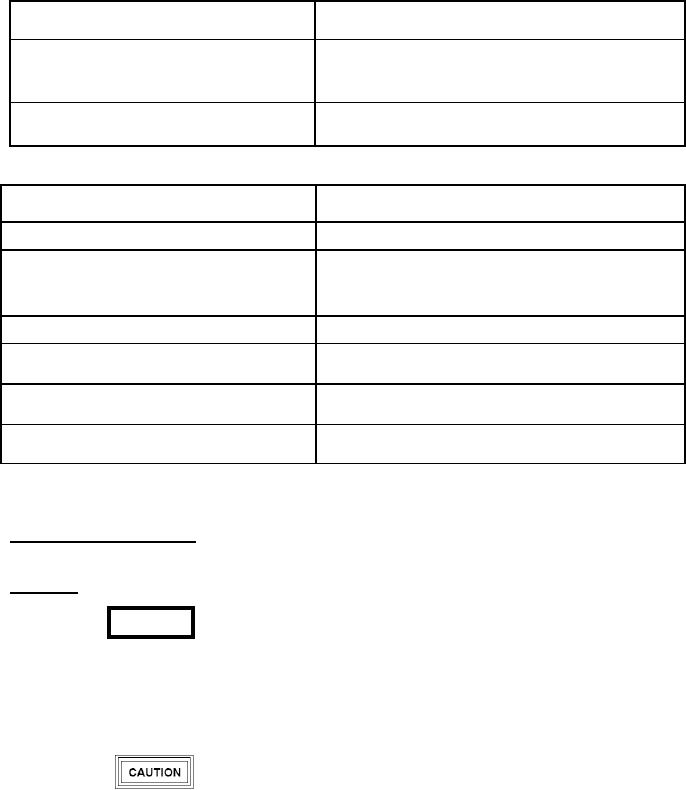
Table 2. Correction of Unacceptable Solder Conditions (Continued)
UNACCEPTABLE CONDITION
CORRECTIVE ACTION
Reheat and pull wire back until the insulation is clear of
Insulation overlapping area of the terminal
the cupped area. Insulation can be against the terminal
but not on it
Reheat and adjust wire toward the terminal until the
Insulation gap exceeds 0.45 inch
insulation gap is acceptable
Table 3. Corrective Actions for Unacceptable Shield Bus Bar Terminations
UNACCEPTABLE CONDITION
CORRECTIVE ACTION
Shield not overlapping bus tab at least 0.20 inch
Reheat and reposition shield
Solder ring still discernible or fillet not formed
Reheat until preform flows, loses ring shape, and wets the
between shield and bus tab
shield and tab
Sleeve so dark that joint is not discernible
Replace solder sleeve
Fillet not discernible between shield and tab due
Replace solder sleeve
to wicking
Shield braiding puncturing or protruding into
Remove sleeve; smooth braiding. Re-solder with new
sleeve
sleeve
Remove sleeve, replace wire as necessary, and re-solder
Sleeve or insulation burned or damaged
with new sleeve
43. CONNECTOR COUPLING. Mating connectors
engage at even a minimum angle may result in
must be correctly aligned and securely attached.
damage to the pins.
44. Alignment.
a. Alignment consists of matching the key and
keyway (remove dust covers to see key and/ or
WARNING
keyways). Before positioning the mating connectors
together, check key and keyway alignment (Figure 11,
Before coupling connectors, insure that all
detail J) and ensure their correct positioning.
related circuits, including battery power, are
de-energized and applicable circuit breakers
b. On a wafer connector, the A-wafer pins go
are open to prevent severe shock or death to
into a wafer sockets. Also, the keys must mate. On
personnel.
wafer connectors, the keys are plastic inserts which
can be keyed (Figure 11, detail J) when installing new
connectors.
c. Wafer connectors mate by pushing the
correctly aligned plug into the receptacle. The
Insure that pins are straight before inserting a
matched joint is secured with screws and nuts on the
plug into a receptacle; forcing the plug to
sides of the connectors. Spacers may be added or