
NAVAIR 01-1A-505-3
TO 1-1A-14-3
TM 1-1500-323-24-3
014 02
1 September 2011
Page 10
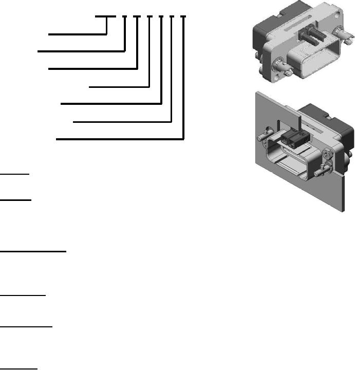
EPXB 1 W B 0 5 K
EPXB Type
Shell Size
Shell Style
Shell Mounting Option
Plug
Locking Device
Polarization Code
Shell Plating
Shell Size
1 Number of insert locations
Shell Style
P Plug (Without Grounding Block)
Receptacle
R Receptacle (Without Grounding Block)
W - Plug (With Grounding Block)
Z Receptacle (With Grounding Block and ground fingers)
CAUTION
EPX A and B aluminum shells are electrolytic nickel over electroless
Shell Mounting Option
B No Mounting Holes
nickel finished. These parts do not meet the minimum salt fog test
M Panel rear mounted connector
required for military use. If installed additional inspection and
(With 2 X 6.32 mounting holes)
corrosion prevention measures are required to maintain system
integrity. Platform Cognizant Engineering Authority (CEA) must use
accepted Reliability Centered Maintenance (RCM) methods to
determine correct inspection cycle and correct treatment interval.
Locking Device
0 Quarter Turn Fastener
Polarization Code
4 Shell delivered with polarization hardware unassembled
5 - Shell delivered with no polarization hardware
Shell Plating
M Nickel plated composite
K Electroless Nickel (96 hour Salt Spray)
Refer to specification for current engineering details.
Figure 9. EPXB Shell Size 1 Shell Part Number Breakdown