
NAVAIR 01-1A-505-3
TO 1-1A-14-3
TM 1-1500-323-24-3
014 02
1 September 2011
Page 11
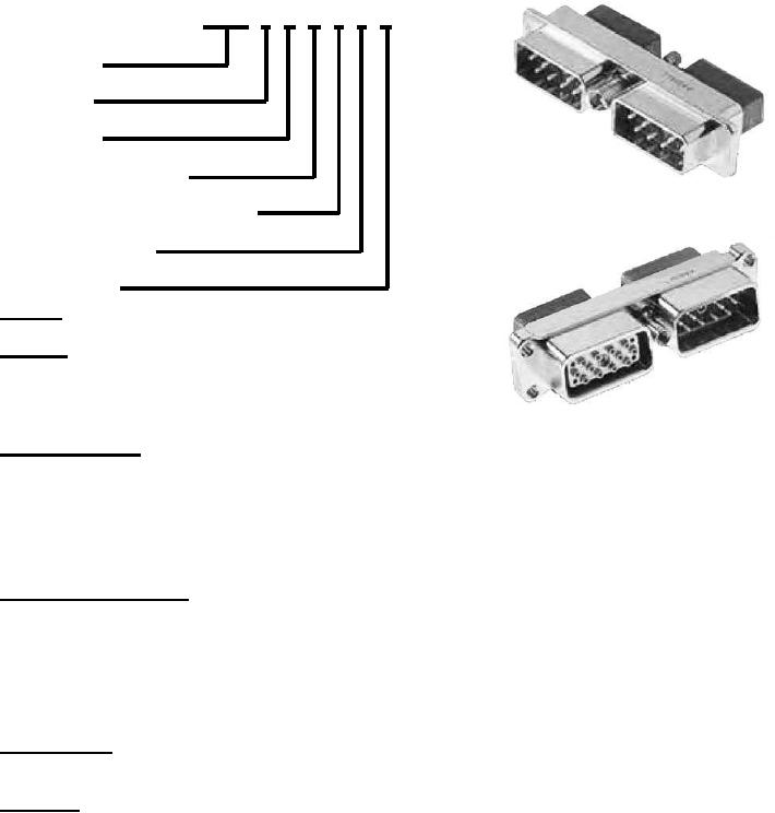
EPXB 2 P B 1 2 N
EPXB Type
Shell Size
Shell Style
Shell Mounting Option
Plug
Locking & Polarization Device
Polarization Code
Shell Plating
Shell Size
2 Number of insert locations
Shell Style
L Receptacle with flange and grounding fingers
P Plug (Without Grounding Block)
R Receptacle (Without Grounding Block)
W - Plug (With Grounding Block)
Z Receptacle (With Grounding Block and ground fingers)
Receptacle
Shell Mounting Option
A - Panel rear mounted connector
(With 4 X 6-32 mounting holes)
B No Mounting Holes
(Locking & Polarization codes 4 & 5 not available)
CAUTION
D Connector with 2 X 3.10 mm thru holes
EPX A and B aluminum shells are electrolytic nickel over
F Panel rear mounted connector
electroless nickel finished. These parts do not meet the
(With 2 X 6-32 mounting holes)
minimum salt fog test required for military use. If installed
L Panel rear mounted connector
additional inspection and corrosion prevention measures
(With 2 X 4-40 mounting holes)
are required to maintain system integrity. Platform
Locking & Polarization Device
Cognizant Engineering Authority (CEA) must use accepted
1 Jackscrew
Reliability Centered Maintenance (RCM) methods to
2 Jacknut
determine correct inspection cycle and correct treatment
(Jackscrew/jacknut can be mounted on plug or receptacle, standard configuration is
interval.
Jackscrew on plug, Jacknut on receptacle.)
3 Without locking device (cancels polarization code)
4 Pin polarization guide for rack and panel application
5 - Socket polarization guide for rack and panel application
(Pin/Socket polarization guides can be mounted on plug or receptacle. However, the
standard configuration pin polarization on plug and socket on receptacle.)
Polarization Code
2 Polarization device A to F delivered unassembled
3 - Polarization device N to Z delivered unassembled
Shell Plating
N Electroless Nickel (96 hour Salt Spray)
Refer to specification for current engineering details.
Figure 10. EPXB Shell Size 2 Shell Part Number Breakdown