
TM 1-1510-262-10
1.
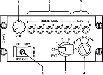
Master Volume Control
2.
Transceiver Audio Monitor Controls
3.
Navigation Receiver Audio Monitor Controls
4.
Microphone Impedance Selector Switch
5.
Transmitter-Intercom Selector Switch
6.
Intercom Mode Selector Switch
A93FE00D0096 C
Figure 3-1. Audio Control Panel
(1) Master volume control. The master volume control, placarded VOL , controls audio volume to individ-
ual headsets.
(2) Transceiver audio monitor controls. The transceiver audio monitor controls, placarded RADIO MON
, 1 through 5, are used to select which transceiver s received audio will be heard in the pilot s or copilot s respective
headset, and its volume. These controls are of the push on, pull off type. Clockwise rotation of a control increases
audio volume to headset.
(a)
RADIO MON 1. Connects user s headset to audio from VHF-AM transceiver number 1.
(b) RADIO MON 2. Connects user s headset to audio from VHF-AM transceiver number 2, or VHF-FM
(SINCGARS) transceiver, as selected by the FM/AM alternate communication selector switch.
(c)
RADIO MON 3. Connects user s headset to audio from #1 UHF transceiver.
(d)
RADIO MON 4. Connects user s headset to audio from HF or VOW transceivers.
(e)
RADIO MON 5. Connects user s headset to audio from #2 UHF transceiver (BU VOW)
(3) Navigation receiver audio monitor controls. The navigation receiver audio monitor controls, plac-
arded RADIO MON, A and B , are used to select which navigation receiver s audio will be heard in the pilot s or
copilot s respective headset, and its volume. These controls are of the push on, pull off type. Clockwise rotation of
a control increases audio output to headset.
(a)
NAV A. Connects user s headset to audio from VOR #1, VOR #2, and marker beacon number 1.
(b)
NAV B. Connects user s headset to audio from TACAN, marker beacon #2, and ADF receivers.
(4) Microphone impedance selector switch. The microphone impedance selector switch, placarded
MIC, 1 - 2 , allows selection of impedance to match microphone being used. Select MIC 1 position for 5-ohm
microphones, and MIC 2 position for 150-ohm microphones.
(5) Transmitter-intercom selector switch. The transmitter-intercom selector switch, placarded PVT, ICS,
1 - 5 , is used to select which transceiver the microphone is connected to when the user s control wheel micro-
phone switch is depressed to the second level or the respective cockpit loor microphone switch is depressed,
and routes the selected transceiver s received audio to the headset, regardless of whether the transceiver audio
monitor control is on or off.
(a)
PVT. This position is not used in this installation.
3-3