
TM 1-1510-262-10
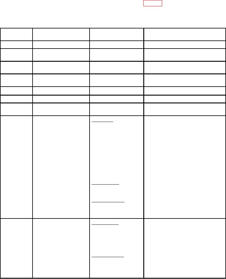
d. Digital Flight Control System Performance/Operating Limits. Table 3-2 contains the digital light control
system performance and operating limits.
Table 3-2.
Digital Flight Control System Limits
CONTROL OR
MODE
SENSOR
PARAMETER
VALUE
Yaw Damper
Yaw Engage
Engage Limit
Up to 45 left or right bank
Autopilot
Engage Limit
A/P Engage
Roll: Up to 15
Engage
Pitch: Up to 20
Touch Control Steering
Roll Control Limit
Roll: Up to 32
(TCS)
Pitch Control Limit
Pitch: Up to 20
Turn Knob
Roll Angle Limit
30
Roll Rate Limit
5.5/sec.
~
Pitch Wheel
Pitch Angle Limit
20
Heading Hold
Roll Angle Limit
Less than 6 and no roll mode selected
Heading
Roll Angle Limit
HDG select knob on the
25
Select
Roll Rate Limit
CRS/HDG control panel
3.0/sec
VOR or
Course knob, NAV receiver CAPTURE
Up to 90
VOR APR
and DME receiver
Beam Angle Intercept
25
(HDG SEL)
5/sec VOR APR
Roll Angle Limit
3/sec VOR
Roll Rate Limit
Course cut Limit at
30 course
Capture
Capture Point
Function of beam, beam rate, course
error, and DME distance. Maximum trip
point is 175 mV. Minimum trip point is
30 mV.
ON COURSE
13
Roll Angle Limit
Up to 45 course error in VOR
Cross Wind Correction
30 in VOR APR
OVER STATION
Up to 30
Course Change
17
Roll Angle Limit
3/sec
Roll Rate Limit
LOC or APR
Course knob, NAV
LOC Capture
Up to 90
or BC
Receiver and Radio
Beam Intercept
25
Altimeter
Roll Angle Limit
5.5/sec
Roll Rate Limit
Function of beam rate and course error.
Capture Point
Maximum trip point is 200mV. Minimum
trip point is 60mV.
13
NAV On Course
30 of course error
Roll Angle Limit
Starts at 1200 ft radio altitude, gain
Cross Wind Correction
reduction = 1 to 0.4
Limit
Gain Programming
3-15