
TM 1-1510-262-10
(7) Trim Annunciators. DN or UP annunciators illuminate when the electric elevator servo is engaged
by the autopilot computer. DN indicates the electric elevator servo is applying nose down trim. UP indicates the
electric elevator servo is applying nose up trim.
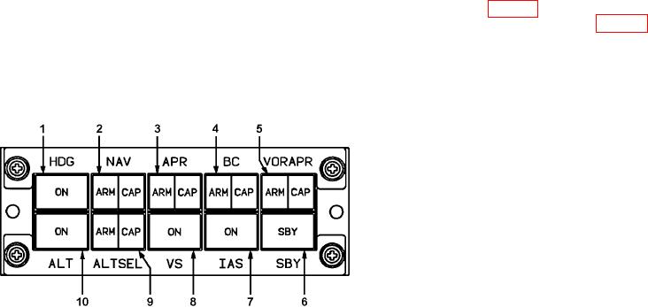
h. Flight Director Mode Selector (MS-207). The light director mode selector (Fig. 3-9), provides all mode
selection except go-around, which is initiated by the go-around switch located on the left power lever (Fig. 2-19).
The light director command bars on the PFD provide integrated pitch and roll guidance to satisfy the selected mode.
The top row of illuminated button-indicators contains the lateral modes, and the bottom row contains the vertical
modes. The split light button-indicators illuminate amber for armed conditions and green for captured conditions.
Mode status is annunciated on both PFD s. If more than one lateral or vertical mode is selected, the light director
system automatically arms and captures the sub mode.
1. Heading Mode Button-Indicator
2. Navigation Mode Button-Indicator
3. Approach Mode Button-Indicator
4. Back Course Mode Button-Indicator
5. VOR Approach Mode Button-Indicator
6. Standby Mode Button-Indicator
7. Indicated Airspeed Hold Mode Button-Indicator
8. Vertical Speed Hold Mode Button-Indicator
9. Altitude Preselect Mode Button-Indicator
10. Attitude Hold Mode Select-Indicator
Figure 3-9. Flight Director Mode Selector/Annunciator
(1) Heading mode button-indicator. Depressing the heading mode button-indicator, placarded HDG , will
illuminate the ON indicator on the face of the switch and will command the light control computer to follow the
inputs of the heading marker located on the heading dial of the coupled PFD.
(2) Navigation mode button-indicator. Depressing the navigation mode button-indicator, placarded NAV
, will cause the light control computer to arm, capture, and track the navigation signal (VOR, LOC, TACAN, or
LNAV) which has been selected as the navigation source for the FMS. When approach (APR ) has been selected,
the navigation (NAV ) select button-indicator will annunciate lateral tracking status.
(3) Approach mode button-indicator. Depressing the approach mode button-indicator, placarded APR ,
will select the appropriate gains to arm and capture the lateral navigation signal for localizer (LOC) and vertical
navigation signals for the glideslope. Except for an ILS, when approach is selected, the NAV switch will annunciate
the appropriate arm or capture condition.
(4) Back course mode button-indicator. Depressing the back course mode button-indicator, placarded
BC , will command the light control computer to track the localizer back course, and will illuminate the ARM or CAP
indicators on the switch face as appropriate.
(5) VOR approach mode button-indicator. Depressing the VOR approach button-indicator, placarded
VOR APR , will select the appropriate gains for capturing and tracking a VOR during the approach phase of light,
and will illuminate the ARM and CAP indicators on the switch face when appropriate.
(6) Standby mode button-indicator. Depressing the standby mode button-indicator, placarded SBY , will
remove all the selected light director modes, forcing the command bars to be removed from the PFD, and will
illuminate the SBY indicator located on the switch face.
(7) Indicated airspeed hold mode button-indicator. Depressing the indicated airspeed hold mode but-
ton-indicator, placarded IAS, will command the system to maintain the current indicated airspeed or to allow a new
indicated airspeed to be selected with either the autopilot pitch wheel or by using the touch control steering switch
on the control wheel. When operating in the IAS mode the ON indicator located on the face of the switch will be
illuminated and the target airspeed will be displayed on the PFD airspeed tape.
3-18