TM 1-7010-386-12&P
CONTROLS AND INDICATORS
0004 00
10
SCSI Address Selector
Selects appropriate SCSI address 0 through 7.
11
Low Temp Indicator Light
Provides visual warning of low temperature conditions which may hinder data
cartridge performance.
12
Condensation Indicator Light
Provides visual warning of condensation present within the SDTMR.
13
Power Indicator Light
Lights to indicate power is applied to the SDTMR.
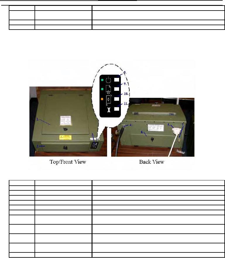
RUGGEDIZED PRINTER ASSEMBLY
Figure 11 illustrates the controls, indicators, and connectors on the Ruggedized Printer Assembly with a brief
description of its function.
Figure 11. Ruggedized Printer Assembly Controls, Indicators, and Connectors
Item No.
Item Name
Description and Use
1
Top Access Cover
Used to access the Print Cartridges and Print Cartridge Cradle.
2
Front Access Cover
Used to access the Paper Trays.
3
Control Panel
Provides status lights and control buttons.
4
DC Power Connector
3 pin male, 25.2 36 VDC Connector.
5
Parallel Connector
The 25 pin connector is provided for connection with the PCU.
6
Rear Access Cover
Provides access to the rear of printer mechanisms.
7
Ground Stud
The ground stud is provided to allow other electronic items to have a common
ground with the Printer.
8
Power Light and Button
Power Button turns the printer on and off. The green light above the Power
Button flashes when printing is in progress.
9
Resume Light and Button
Light flashes when action is required such as loading paper or clearing a paper
jam. When the problem is fixed, press the Resume button to continue printing.
10
Print Cartridge Light and Status
Light flashes when the status of print cartridges needs to be checked or when
print cartridge ink level is low.
11
Cancel Button
Cancels current print job.
0004 00-12

