
TM 10-4930-351-14
0109 00
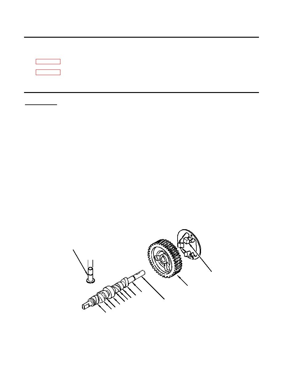
INSTALL CAMSHAFT (Refer to Figures 8 and 9.)
INITIAL SET-UP:
Tools:
Materials/Parts Required
Dial caliper
None
(WP 0113 00, Item 3)
(WP 0113 00, Item 3)
Equipment Condition:
Camshaft and tappets removed
Crankshaft installed
Refer to Figure 8.
1.
Clean and inspect camshaft gear (1) for worn or broken teeth and loose or unserviceable counter weights (2).
2.
Using dial caliper inspect camshaft (3) and bearing surfaces for wear in accordance with the following. If any
measurement is out of tolerance, replace the camshaft.
a.
Valve lifter cams (A) must be no less than 1.366 inches from tip of cam to opposite point.
b.
Flattened injection pump cams (B) must be no less than 1.377 inches from center of flattened area to opposite point.
c.
Fuel pump cam (C) must be no less than 0.984 inches in diameter.
d.
Outer bearing surface (D) must be no less than 0.708 inches in diameter.
e.
Inner bearing surface (E) must be no less than 1.690 inches in diameter.
NOTE
Valve tappets to be reused were marked for reinstallation and should be installed in same
bores.
3.
Using a micrometer check tappets for wear. Small end of tappet (4) (F) must be 0.471-0.472 in. (11.977-11.993 mm) in
diameter. If not within limits, replace tappet (4).
4
F
2
1
D
A
AB
3
C
E
A
B
A
Figure 8. Camshaft Inspection
0109 00-11
