TM 55-1500-345-23
NOTE
Where conditions permit on 1 inch ond 2
inch clamp mounted indicators, which
have the numerals and graduations on the
outer circumference of the dial the fluo-
rescent range marks wilI be installed on
the front edge of the case just outside the
cover glass. In those instances where the
foregoing does not apply refer to the
instrument markings presented in the -10
Operator's Manual.
(5) After allowing the applied marker to air dry for
30 minutes, trim to exact size and paint over the marker with
another coat of varnish.
NOTE
If it is desired to remove any excess var-
nish, this may be done within 1/2 hour
after application with a cloth dampened
with naphtha.
NOTE
The following paragraphs describing the
markings for the various types of instru-
b. INDEX MARK. A white index mark not over 1/16-
inch wide will be painted across the joint between the glass
ments attempt to cover all possible mark-
ings for each instrument. It should be
and the case at the bottom of the center (6 o' clock) position,
noted that the illustrated instruments are
or in the uncalibrated area of all instruments having range
typical and may or may not include all the
markings on the glass. On panel installed clamp mount type
markings mentioned in the descriptive
instruments, the mark will be extended across the edge of
the instrument case onto the mounting panel. On clamp
paragraphs.
mount type instruments, not panel installed, the mark will be
extended across the rim of the case, onto the case. On instru-
NOTE
ments utilizing the entire circumference of the dial for cali-
It is not intended in this technical manual
bration increments the location of the index mark will be
left to the discretion of the using activity.
to set forth the exact ranges to be covered
by these instrument markings for all air-
craft but to illustrate the correct method of
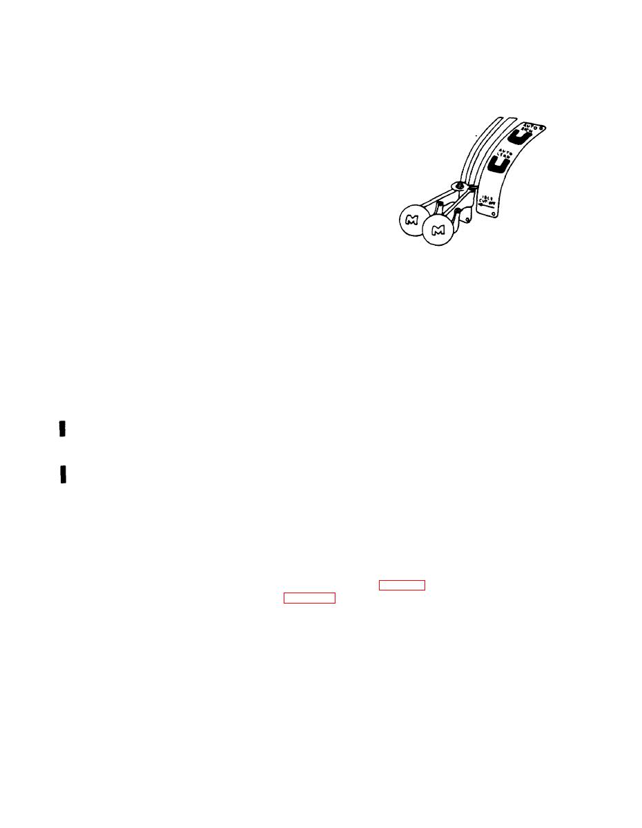
c. MIXTURE CONTROL QUADRANT MARKINGS.
marking the various types of instruments.
Mark the automatic lean position with gloss cellulose nitrate
For example, the manifold pressure gage
lacquer, light blue, Federal Specification TT-L-32. Mark the
automatic rich position with gloss cellulose nitrate lacquer,
of 49 inches; for one aircraft it might be
light green, Federal Specification TT-L-32. (See figure 7-5).
55 inches; for another it might be 72 inch-
es; for another, 100 inches, and the like.
The exact ranges to be covered on each
instrument for a given aircraft can by
determined only through reference to the
instrument marking page of the appropri-
ate -10 Operator's Manual.
7-19


