TM 55-1500-345-23
MARKINGS
FOR
JET
ENGINE
AIRCRAFT
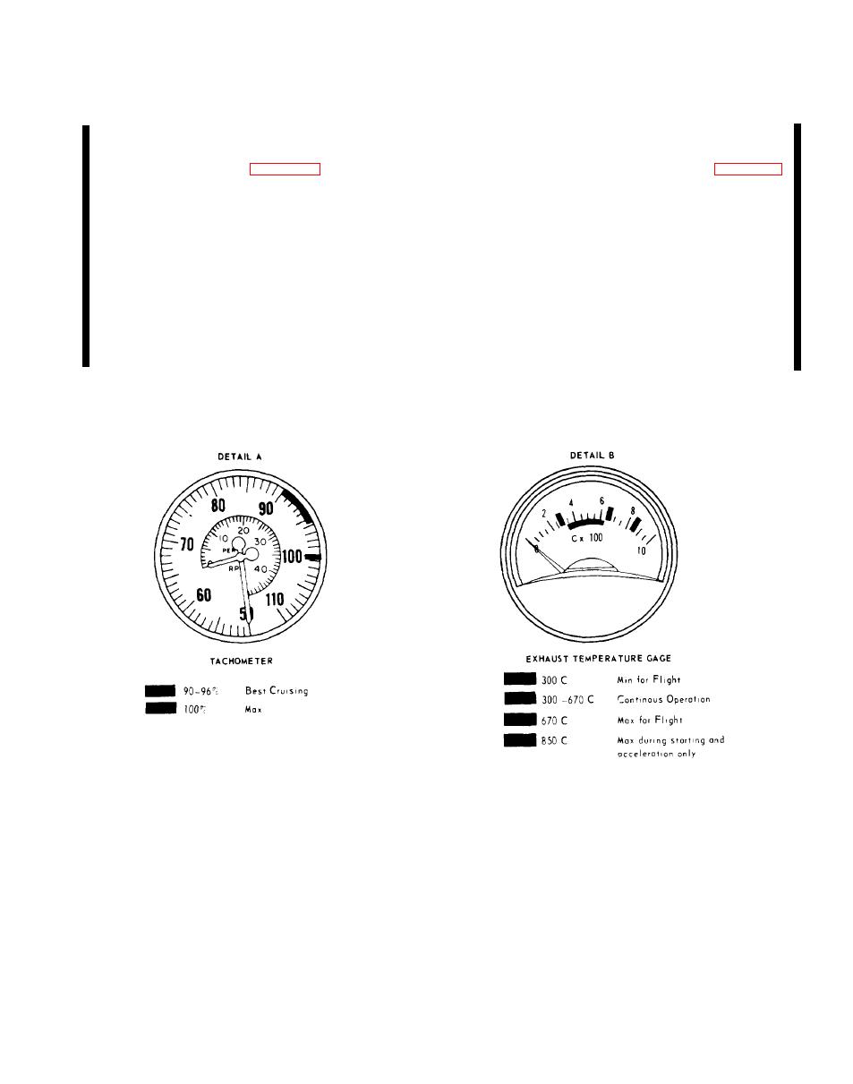
detail B.)
(1) GREEN ARC. Describes the range within which
(1) RED RADIAL. Indicates minimum permissible
the rpm must falI during continuous flight operation.
temperature during flight.
The bottom of this arc describes the minimum rpm
for best cruising. Considerable range will be lost
(2) GREEN ARC. Indicates desirable temperature
when operating below this rpm. The top of this arc
indicates maximum continuous rpm; operation above
during continuous operation.
which is limited to a specified length of time.
(3) RED RADIAL. Indicates maximum permissible
(2) RED RADIAL. Indicates maximum rpm.
temperature for flight.
(3) RED ARC. May be used to show region of pro-
(4) RED RADIAL. Indicates maximum permissible
hibited operation because of dangerous vibration or
temperature during starting or acceleration.
similar reasons.


