TM 55-1500-345-23
CODE
WORDING
NO
DIRECTIONS
DRIVE SHAFT
21
Left side of drive shaft cover. (Not applicable
ACCESS
to IR aircraft.) 1/2-in. black letters.
22
TAIL ROTOR
Locate parallel to ground below tail rotor tie
TIE DOWN
down loop. 1/2-in. black letters.
12345
Radio call numbers are 17-1/2 in. above tail
23
skid fairing and parallel to the ground, 6 in.
high, black numbers, both sides.
24
FUEL CROSSOVER TRAP DRAIN
Size 1 in. x 13 in. with 1/4-in. black letters.
Locate outboard of drain, top of Ietters
inboard.
HYDRAULIC RESERVOIR
25
Size 1-7/8 in. x 10-7/8 in. with 1/2-in. black
SCRUPPER & PUMP CASE
letters on RH side fwd of crossover tube. Top
DRAIN
of letters inboard.
NO PUSH
26
Both sides of tail boom fairing 1/2-in. black
letters.
FOR AIR TRANSPORT
Locate both sides of tail boom and as close
27
TIE DOWN ONLY
to fitting as possible, 1/4-in. black letters.
28
Size 1 in. x 4-5/8 in. with 1/2-in. black letters.
HEATER DRAIN
Center of caption aft and against drains with
top of letters inboard, (if applicable).
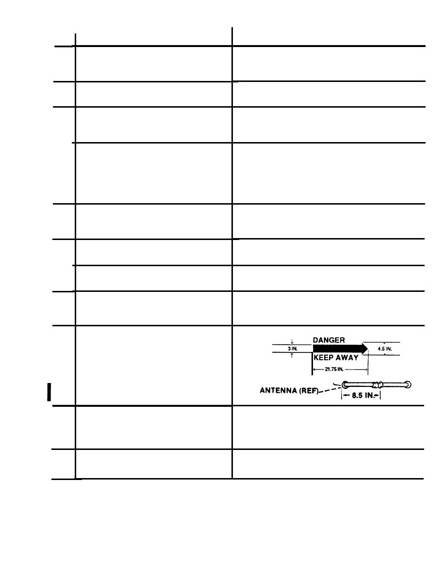
TAIL ROTOR WARNING.
29
Black arrow 3 in. wide, 21.75 in. long in-
cluding 4 x 4-1/2 in. arrow head. Locate arrow
4 in. above parallel with centerline of
antenna extending 8.5 in. past forward end of
antenna mount. 1-3/4 black letters. See
detail B.
HEATER FUEL CONTROL BOX DRAIN
30
Size 2-3/8 x 7-5/8 in. transparent background
with 1/2 in. black letters. Located outboard of
drainwith tops of letters facing fwd, (if applic-
able).
HEATER FUEL PUMP DRAIN
31
Size 1-7/8 x 4-1/2 in. transparent background
with 1/2 in. black letters. Located aft of drain
with tops of letters inboard, (if applicable).
Figure 9-30. Exterior Markings, UH-1C and UH-1M (Sheet 8 of 17)
Change 5
9-141


