
TM 55-1510-215-10
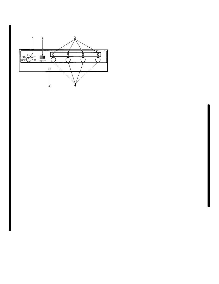
1.
Function selector switch
2.
Reply annunciator
3.
Code windows
4.
Control knobs
5.
Ident button
AP011845
Figure 3-18. Transponder (KT 76A)
When the function selector switch is held in the TST
(5) IDENT button. The IDENT button feature
position the reply annunciator should illuminate and
is used at the request of the traffic controller The IDENT
remain illuminated until the selector switch is placed in
button is depressed momentarily and then released. A
another position. This provides for a integral test of the
memory holds the IDENT reply for an interval to assure
unit.
the proper reply for at least one radar sweep. This
memory also turns the reply lamp on steady as an
(2) Reply annunciator.
During normal
indication of the ident function.
transponder operation, a flashing annunciator is an
c. Operating Procedures.
indication of a transmitted reply. An interrogation will
normally be at 10-15 second intervals Flashes within this
1. AVIONICS MASTER switch - ON.
interval may be from noise, a second or third
2. Transponder reply code - Set as
interrogator, or from side lobes (from interrogators
required.
without side lobe suppression). When the IDENT button
3. Function selector switch - SBY
is depressed the reply annunciator will glow steady as
(allow time for warm up).
an indication of the ident function.
4. Function selector switch - ON or
ALT prior to takeoff.
(3) Code windows.
Displays transponder
5. Ident button - Depress as required.
reply codes as selected with the control knobs.
d. Shutdown Procedure.
(4) Control knobs. The control knobs are
1. Function selector switch - OFF.
used to select the desired transponder reply codes.
2. AVIONICS MASTER switch - OFF.
Attention should be paid to the code selected. The
selected code should be in accordance with instructions
for IFR flight or rules applicable to transponder utilization
for VFR flight. Unless required, avoid selecting 7700,
7600, or 7500 codes. These codes are for emergencies,
loss of communications, and hijacking respectively.
3-32 Change 5
