TM 55-1510-215-10
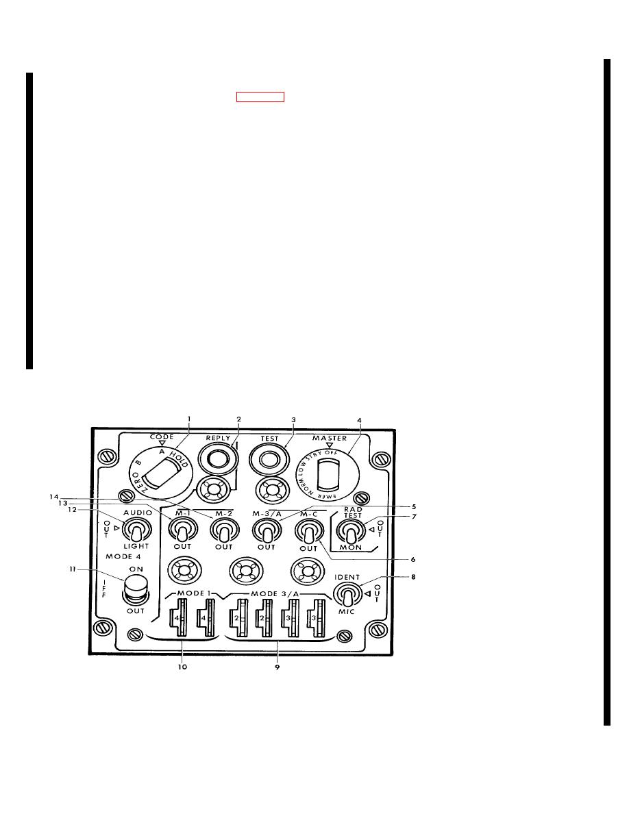
(2) REPLY light. Indicates valid mode 4
3-29. Transponder Set (AN/APX-72) (If installed).
interrogations and replies when MODE 4 AUDIO LIGHT
switch is in AUDIO or LIGHT positions.
an identification, position tracking, and emergency
tracking device. This set receives, decodes. and
(3) TEST light. Indicates the proper response
responds to interrogations by search radar. It operates
has been generated when the M-1, M-2, M-3/A, and M-C
in conjunction with a TS-1843/APX inflight test set which
switches are placed in TEST position. Also illuminates
provides a self test feature, and a KIT-1A/TSEC
when RAD TEST-MON switch is in MON position and
computer which provides mode 4 feature. Power for the
replies are made to M-1, M-2, or M-3/A interrogations.
system is fed through two 50-ampere circuit breakers,
placarded AVIONICS 1 and AVIONICS 2, located on the
(4) MASTER control.
Provides a means of
copilot's circuit breaker panel. The system is protected
selecting the following:
by a 10-ampere circuit breaker, placarded XPDR 2,
located on the right subpanel.
(a) OFF position. Turns set off.
(b) STBY position. Places set in warm-
b. Controls and Functions.
up (standby) condition.
(1) CODE control. Selects mode 4 code of
(c) LOW position. Places set at low
the day, A or B.
sensitivity.
(d) NORM position. Operates set at
(a) HOLD position. Prevents zeroizing
normal sensitivity.
when power is removed from the set or MASTER control
(e) EMER
position.
Transmits
is turned OFF.
emergency reply.
(b) A position. Selects keyed in code A.
(5) M-1, M-2, M-3/A and M-C switches.
(c) B position. Selects keyed in code B.
Provides a means of selecting the following:
1.
CODE control
2.
REPLY light
3.
TEST light
4.
MASTER control
5.
M3/A switch
6.
M-C switch
7.
RAD TEST-MON switch
8.
IDENT-MIC switch
9.
MODE 3.A code selector
10.
MODE 1 code selectors
11.
MODE 4 ON-OUT switch
12.
MODE 4 AUTO-LIGHT switch
13.
M-1 switch
14.
M-2 switch
Figure 3-19. Transponder Control Panel (AN/APX-72)
Change 5 3-33


