
TM 55-1510-215-10
e. Shutdown Procedures.
system are slipped to assure the pilot can overpower the
autopilot at all times. The system is protected by a 10-
1. OFF
VOL
switch
-
Turn
ampere circuit breaker placarded AP/FD, and a 1-
counterclockwise to off (detent).
ampere circuit breaker placarded YAW, both located on
2. AVIONICS MASTER switch - OFF.
the copilot's circuit breaker panel (fig. 2-18).
b. Modes of Operation.
3-27. Flight Control System (KFC 250).
(1) Flight director (FD). The flight director
a. Description.
The flight control system is
mode is activated by depressing the FD button on the
functionally divided into four parts: sense, compute,
mode controller (fig. 3-17). FLT DIR will display in the
display, and control. All sensor information (pitch and
mode annunciator panel located on the pilot's instrument
roll reference. slaved compass, RNAV/VOR/ LOC/GS,
panel (fig. 2-22). The FDI command V-bar will appear,
DME, marker receiver, and air data) is fed into a flight
providing the pilot with steering commands, to maintain
computer. The flight computer computes pitch and roll
wings level and pitch attitude that existed at the time of
commands. These commands are routed to the pilot's
flight director engagement. If pitch or roll attitudes are
flight director indicator (fig. 3-10), where they are
changed, recycling the FD button will synchronize the
displayed on the command V-bar as visual steering
command V-bar to the new position.
commands. These steering commands are also fed to
the autopilot computation circuits contained in the flight
If a change in the commanded pitch attitude is
computer, where the steering commands and aircraft
desired, the control wheel steering (CWS) button,
yaw rate information are combined to generate the
installed on both (pilot and copilot) control wheels, allows
aileron, elevator trim, and rudder drive commands for the
the pilot or copilot to manually synchronize the command
autopilot.
V-bar. The vertical trim switch on the mode controller
may also be used to adjust the selected pitch attitude up
Each servo used in the system incorporates a
or down at approximately 1-degree/per second.
clutch, which allows for manually overriding the controls.
During the autopilot preflight check, all clutches in the
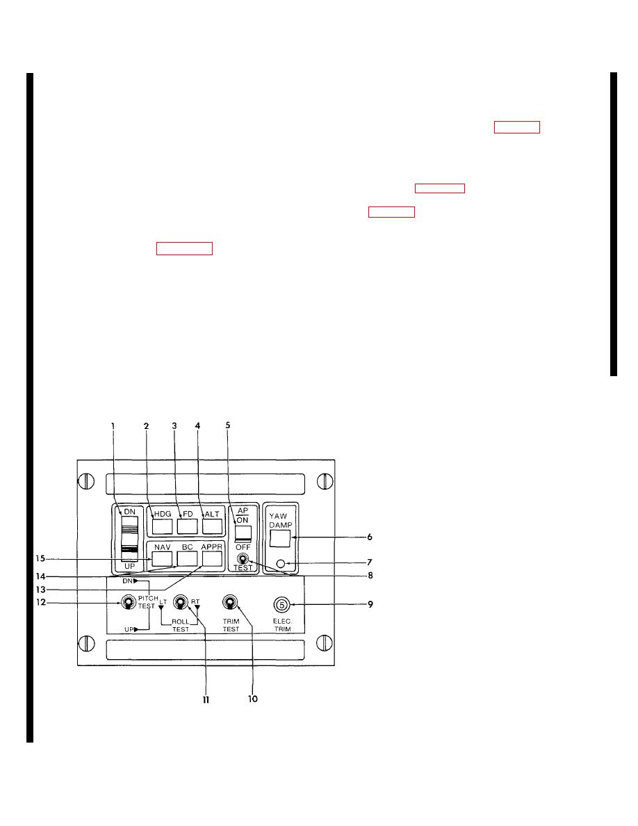
1.
Vertical trim switch
2.
Heading (HDG) button
3.
Flight director (FD) button
4.
Altitude (ALT) button
5.
Autopilot switch
6.
Yaw damp switch
7.
Yaw damp annunciator
8.
Autopilot test switch
9.
ELEC TRIM circuit breaker
10.
TRIM TEST switch
11.
ROLL TEST switch
12.
PITCH TEST switch
13.
Approach (APPR) button
14.
Back course (BC) button
15.
Navigation (NAV) button
Figure 3-17. Mode Controller
3-28 Change 5
