TM 55-2840-241-23
Change 19 5-25
(5)
With the engine at 100% N2 and the com-
pressor bleed valve closed, set the friction lock on collec-
tive and rotate the twist grip to flight idle and let N1 stabi-
lize. The bleed valve should be fully open.
(6)
Slowly rotate the twist grip toward open. Re-
cord the N1 speed at which the compressor bleed valve
starts to close.
(7)
Continue rotating the twist grip and record N1
speed at which the compressor bleed valve is fully
closed.
(8)
Compare the recorded N1 speeds for figure
1-8. Clean the compressor bleed valve (refer to para 7-7)
if range of figure 1-8 is not met and retest. Replace the
bleed valve if it does not operate within the range on
figure 1-8.
b. Removal.
(1)
Disconnect the compressor discharge pres-
sure sensing tube (1, figure 5-13) at compressor bleed
valve (5). (Disconnect tube at the diffuser scroll pressure
probe elbow only if necessary.)
(2)
Remove three nuts (9,12), bolts (6,10) and
washers (7, 11); remove valve (5) and gasket (8). Discard
the gasket.
(3)
If valve is to be replaced, remove lockwire,
loosen jam nut (3) and unscrew elbow (2) from the bleed
valve. Discard preformed packing (4).
c. Installation.
(1)
Install compressor bleed valve (5) and new
gasket (8) on mounting flange. Retain with three nuts (9,
12), bolts (6, 10) and washers (7, 11).
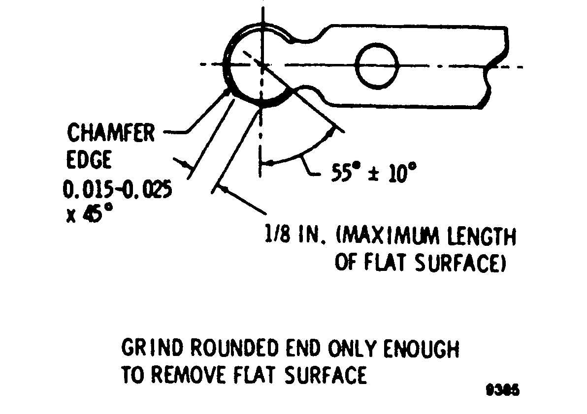
Figure 5-15. Anti-icing Valve Lever Repair
Apply antiseize compound (item 15, table 2-2) to
the bolts. The 1/4-28 bolt goes in the left hole (looking
forward). Tighten nut on 1/4-28 bolt to 70-85 in. lb. and
the other two nuts to 35-40 in. lb.
(2)
Lubricate preformed packing (4) with oil (item
7, table 2-2) and place on elbow (2). Install the elbow in
the bleed valve. Do not tighten the jam nut.
(3)
Attach compressor discharge pressure
sensing tube (1) to valve elbow (2). Tighten coupling nut
to 80-120 in. lb. Tighten jam nut (3) to 55-80 in. lb.
Section V. IGNITION SYSTEM
5-34. Scope.
Ignition system servicing includes replacing and test-
ing the ignition exciter, spark igniter and igniter lead.
5-35. Ignition Exciter.
a. Removal.
WARNING
The ignition unit contains a very small
amount of radioactive material (cesium-
barium 137) and normally requires no han-
dling precautions. However, severely
damaged units that have been broken
open, must be handled with forceps or
lead gloves and disposed of in accor-
dance with TB 43-0108 and AR 11-9.
WARNING
To prevent personnel injury due to electri-
cal shock, ensure ignition system has
been off at least five minutes before dis-
connecting any leads. Ground leads to en-
gine using an insulated screwdriver.
(1)
Remove nut (1, figure 5-16) and washer (2)
and disconnect power input lead from the exciter (3).
(2)
Disconnect igniter lead (18) from the exciter.
(3)
Remove three nuts (4) and washers (5) se-
curing exciter (3) to the gearbox housing. Remove the
exciter.
b. Inspection.
(1)
Visually inspect for general condition of excit-
er, input power terminal, and igniter lead connector.
Nicks, dents, etc. are acceptable if damage does not
extend through the case or cover. Bent or misaligned
electrical connector is acceptable if the connector base
is not excessively distorted, bulged, or cracked. The con-
nector ends must assemble properly with no evidence of
internal damage.


