TM 55–2840–254–23
5–58 Change 6
5–11 INSTALL ACCESSORY GEAR ASSEMBLY (AVIM) (Continued)
5–11
4.
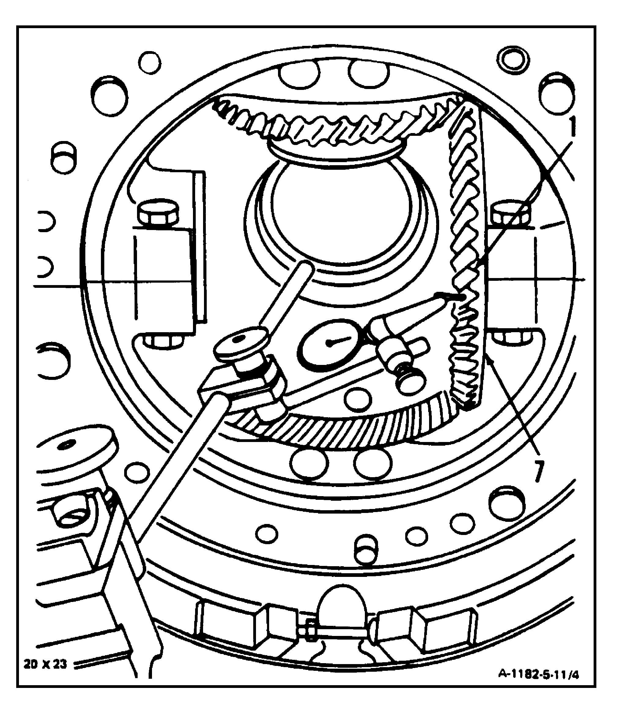
Have helper hold locating bar (T1)
steadily across inlet housing.
5.
Place dial indicator on locating bar (T1).
Place pointer on center of bevel gear
tooth (1).
6.
Check backlash of bevel gear (7) and
compressor rotor pinion gear. Backlash
shall not be less than 0.007 inch or
greater than 0.013 inch. Record back-
lash.
7.
Remove dial indicator and locating bar
(T1) from inlet housing.
8.
Rotate compressor shaft counterclock-
wise three complete revolutions.
9.
Turn engine to horizontal position.
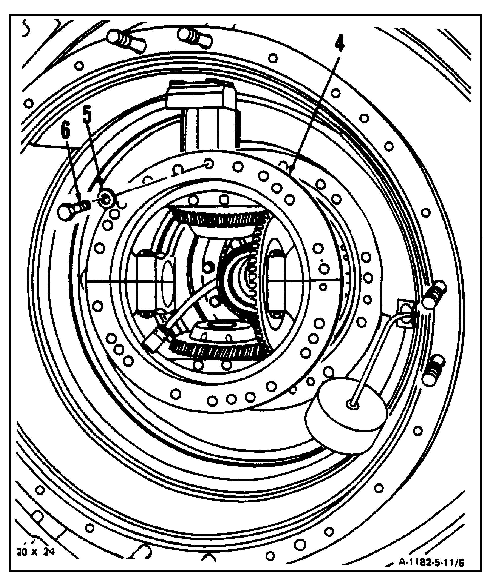
10. Remove four bolts (6) and four washers
(5) from accessory gear assembly (4).
GO TO NEXT PAGE