TM 55-4920-328-13
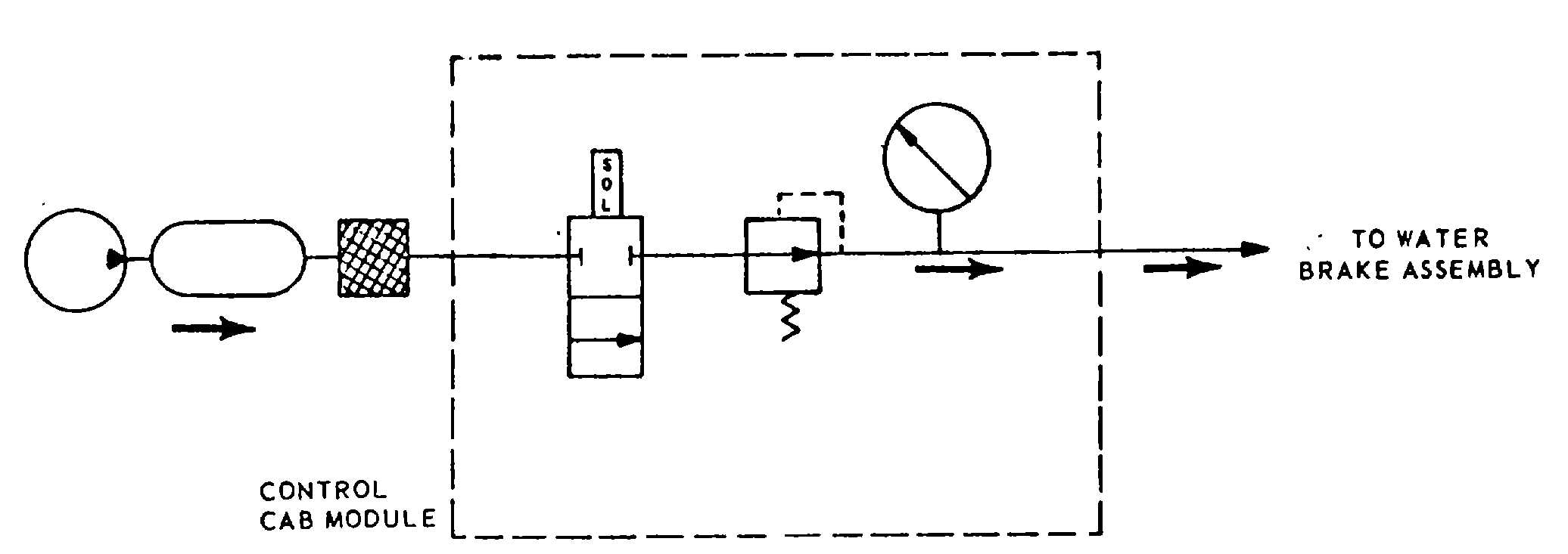
Figure 1-20. Test Trailer Air System Schematic Diagram.
Diagnostic Sub-Module (Unit 1) (13) (e)
Analyzer Sub-Module (Unit 2) (20) (f)
Operator's Sub-Module (Unit 3) (18) (g)
Services Sub-Module (Unit 4) (17) (h)
Control Power Module (Unit 5) (15) (i)
Starter and Contactor Compartment (Unit 6)
(24) (a)
Barrier Strip Junction Box Assembly (Unit 7)
(10) (d)
Left Hand Castle Assembly (Unit 8) (14) (j)
Right Hand Castle Assembly (Unit 9) (16) (k)
Test Trailer Bulkhead Box Assembly (Unit
10) (11) (d)
Generator Fault Indicator Panel (22) (b)
Generator Control Panel (23) (b)
Circuit Breaker Panel Assembly (25) (c)
(a) Starter and contactor compartment (unit
6). The starter and contactor compartment (24, figure 1-
21), located below the rear writing surface assembly in
the control cab module, houses the 4 starters and 2
contactors used in the METS auxiliary systems, except
for the water system. The six units are essentially
heavy-duty relays consisting of two or more sets of
magnetic
contacts,
depending
on
the
service
requirements of each circuit. With the exception of
starter K5 used in the oil preheat circuit and contactor
K6 used in the trickle charger circuit, all units are
provided with thermal element overload protection. The
oil preheat circuit is not provided with a set of overload
contacts; the other five are so equipped. These
overload contacts open on an overload to remove
ground from the relay coil to deenergize the relay and
disable the affected circuit. Refer to chapter 5 for circuit
information on the six starters and contactors. The units
identified by reference designations are used in the
following circuits:
K1 Air System Compressor Motor
K2 Fuel System Pump Motor
K3 Oil System Pump Motor
K4 Portable Oil Unit Pump Motor
K5 Oil System Oil Pre-Heat Unit
K6 Electric Start System Trickle Charger
(b) Generator control and fault indicator
panels. Primary electrical power, provided by the
generator set mounted on the auxiliary trailer assembly,
is remotely controlled within the control cab assembly.
The generator control panel (23, figure 1-21) and
generator fault indicator panel (22) were originally
installed in the diesel engine generator set on the
auxiliary trailer assembly. For operator convenience,
these panels have been relocated within the control cab
assembly. The controls and indicators for each panel
are located and identified in figure 2-8. Refer to TM 5-
6115425-12 for further information.
(c)
Control
cab
circuit
breaker
panel
assembly. The circuit breaker panel assembly (25,
figure 1-21) consists of a rectangular panel assembly
and enclosure which mounts a main ac circuit breaker
and 13 facility service circuit breakers. Contained in the
panel are 5 triple-pole circuit breakers, 3 double-pole
circuit breakers, and 6 single-pole circuit breakers. After
the main ac circuit breaker is energized the 13 auxiliary)
service circuit breakers can be energized as required to
supply power to the control power module switches
contained in Unit 5. The circuit breakers listed below
control the following facility services and systems:
1-25