TM 55-4920-328-13
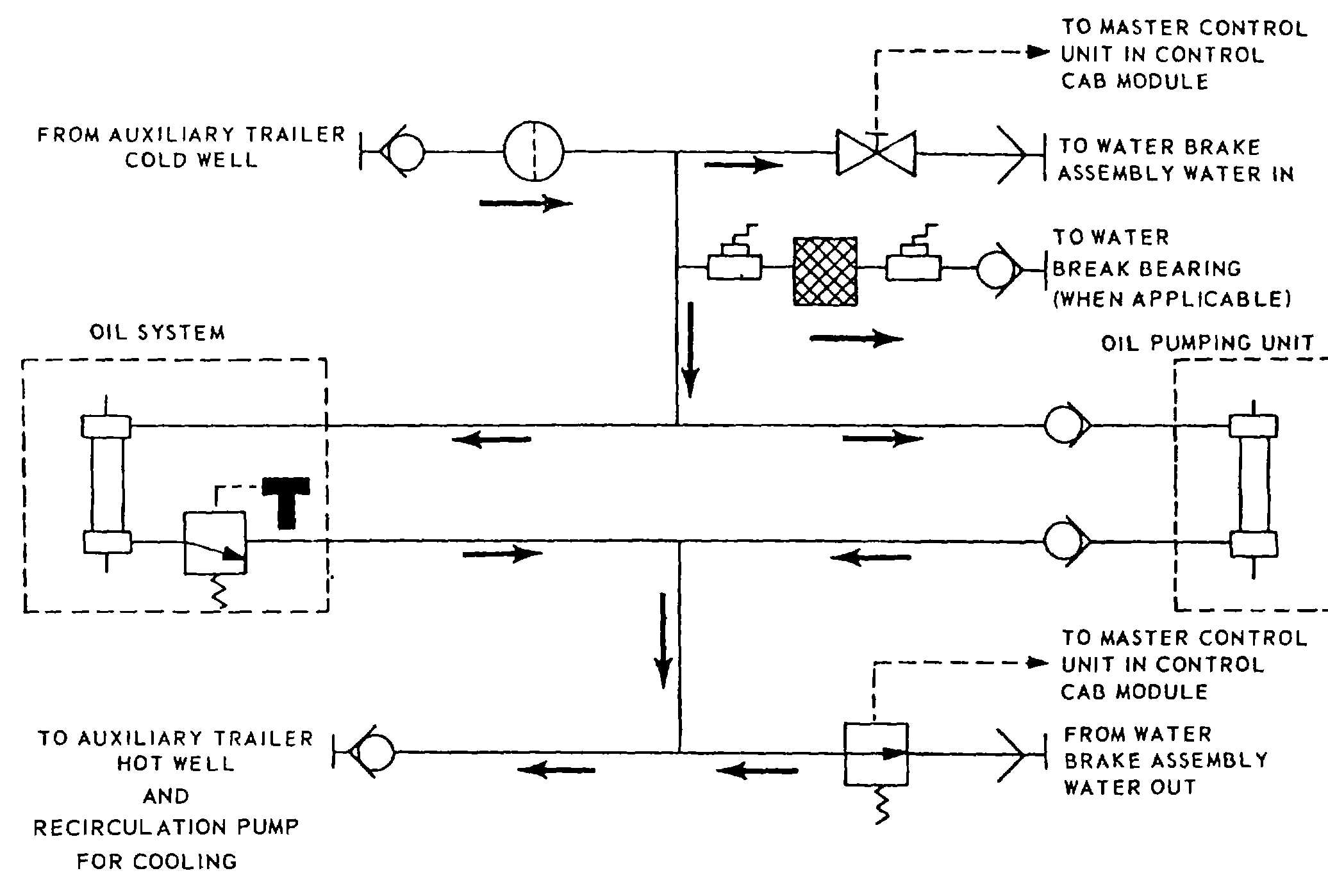
Figure 1-17. Test Trailer Water System Diagram.
tested. The air system (shown schematically in figure 1-
20) consists essentially of a compressor assembly
(figure 1-19) and an air storage tank 15. figure 1-18).
The compressor assembly (1) is mounted on top of the
fuel tank. The storage tank is installed below the fuel
tank. The air system is operated by 208v ac, three-
phase, 60 Hz electrical power supplied from the
generator set. The compressor assembly consists of a
5-horsepower electric motor (1, figure 1-19) and an air
compressor (4). An automatic regulating pressure
switch (2) starts the motor at 125 psig and stops the
motor at 150 psig. If the pressure switch malfunctions to
cause excessive pressure buildup, a safety valve (7,
figure 1-18) on the air storage tank is set to relieve at
175 psig. A drain valve (8) is installed on the bottom of
the air storage tank (5) for drainage of condensate.
(b) The air system is energized through the
air compressor circuit breaker CB1 (15, figure 29) and
the AIR COMP START switch S11 (12, figure 1-26).
This action energizes the coil of relay K1 in the air
system circuitry to provide 208v ac, 60 Hz, three-phase
power to the motor of the air compressor. The AIR
COMP STOP switch S12 (26) is depressed to disrupt
the circuit to the relay coil to stop the motor at the end of
an engine test cycle. The two-stage compressor
provides pressurized air to the storage tank at 125 to
150 psig. A manually operated pressure regulator (6,
figure 127) and an air pressure gage (8) in the right
hand castle assembly permit the test technician to
regulate air pressure to the water brake assembly at the
specified pressure. Refer to chapter 3 of this manual for
operating instructions for the air system.
(11) Control cab assembly. The control cab
assembly (figure 1-21 ) consists of a rectangular control
cab module which contains essentially all of the controls
and instrumentation required for METS operation. The
control cab assembly is comprised of the following
significant components, subsequently described in the
referenced sub-paragraphs:
Control Cab Module (1) (d)
1-22