TM 55-4920-328-13
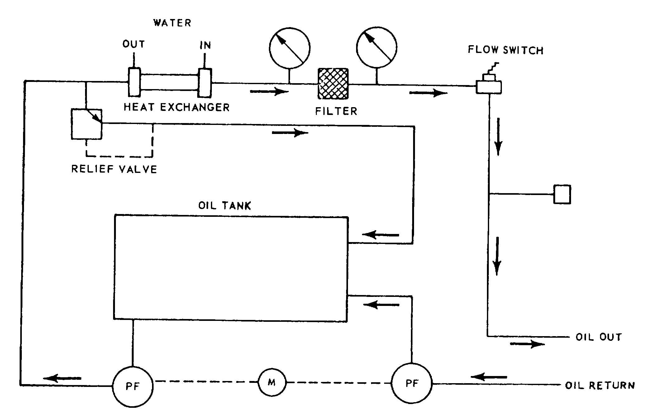
Figure 1-15. Portable Oil Unit Schematic Diagram.
operated by action of the hydraulic servo loops
controlled by two master control units (19, figure 1-21) in
the control cab module. These master control units are
installed on the forward writing surface assembly (12,
figure 1-21).
(b) As shown schematically in figure 1-17,
inlet water under pressure is obtained from the cold well
on the auxiliary trailer through a 30-foot long hose
assembly. Four supply and three return branches are
connected to the system downstream from the strainer.
The water brake assembly water-in branch is routed
through the hydraulically-controlled inlet control valve
and terminates in a quick-disconnect fitting. A second
branch is routed through the filter and in-line flow
switches and terminates at a quick-disconnect fitting to
which a water brake bearing supply hose, assembly is
connected prior to a test. The water system supply line
then divides to branch through the oil system heat
exchanger and oil system temperature regulating valve,
and also flows through the heat exchanger in the
portable oil unit. These branches and the water brake
assembly water out branch converge at the return leg of
the system which terminates at a quick-disconnect
fitting. A second 30-foot long hose assembly transfers
the heated water from the two heat exchangers and
from the water brake assembly to the auxiliary trailer hot
water well. The flow switch to be used depends on the
particular engine being tested One of the two normally-
closed spat flow switches opens on increasing flow of
4.0 to 4.4 gpm. The other flow switch opens on
increasing flow of 0.9 to 1.3 gpm. Closure of the flow
switch during water system operation completes a circuit
to illuminate the WATER BRAKE BRG H2O indicator
DS5 (21, figure 1-25) on the ALARM DISPLAY section
of the upper panel assembly on the services sub-
module. This action simultaneously causes the audible
alarm to sound to alert the test technician of a low flow
condition. Controls for operation of the water system
are depicted in figure 1-26 and are located on the No. 1
power control panel assembly.
(10) Test trailer air system.
(a) The test trailer air system (figure 1-18)
provides pressurized air to the water brake assembly
when testing certain engines, and to the PI air bellows
connection when a T53 engine is to be
1-20 Change 3


