TM 1-1500-204-23-1
6
Set calibrated scale until zero mark
on scale and scribe on pointer are aligned.
7
Move pointer back to top of slot or
until it contacts pivot arm.
8
Turn
crankshaft
in
direction
opposite normal rotation until pivot arm returns to top of
slot.
9
Recheck zero mark of calibrated
scale against reference mark on slide pointer.
10
Move slide pointer to top of slot or
until it contacts pivot arm.
11
Rotate crankshaft In direction of
rotation. Movement of slide pointer by the pivot arm will
Indicate crankshaft position In relation to true top dead
center on the calibrated scale.
(e)
Alternate methods of locating leaky
intake exhaust valves. Alternate methods of locating
leaky intake and exhaust valves are listed In the following
paragraphs.
1
Engine run test. Prior to stopping
engine, run it up to 1000 rpm and move mixture control to
IDLE CUT-OFF. The engine will turn over six or more
revolutions after combustion ceases. A very slight
burning of an exhaust valve will be evidenced by a
pronounced slush from the affected cylinder This sound
occurs each second revolution of the engine.
2
Wheeze test Perform wheeze test
for locating leaky intake and exhaust valves by pulling
piston to top dead center, locate faulty valve by listening
for noise in exhaust collector or Intake duct which
indicates air leaking past respective valve.
3
Compressed
air
test
Admit
compressed air into cylinder through spark plug hole
Restrain piston at top of dead center Locate leaking valve
by listening for noise in exhaust collector and intake duct.
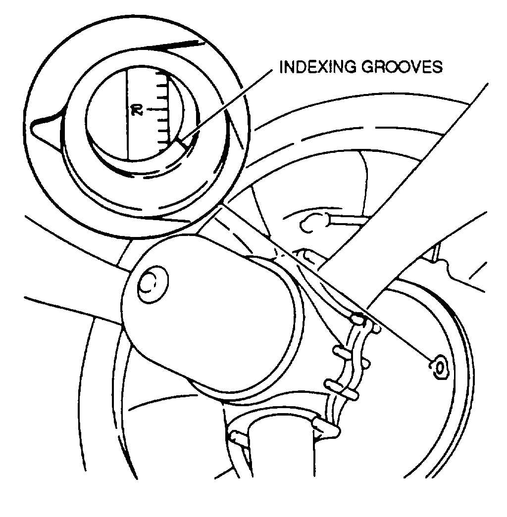
(f)
Built-m timing marks. Some engines
have reference timing marks built into the engine, as
shown in figure 7-17. Engines without a propeller
reduction gear will have the timing mark, a scribe mark or
a pin, on the propeller shaft and a corresponding
reference mark on the surface of the nose section next to
the shaft. Refer to the applicable maintenance manual
for location of such marks.
NOTE
When using timing marks to position
the crankshaft, sight straight across
the stationary pointer or mark on the
nose section to the other mark. Any
angle incurred in sighting will cause
error when positioning the crankshaft.
h.
Accessories. Accessory units such as fuel
pumps,
vacuum
pumps,
oil
pumps,
generators,
alternators, magnetos, starters, filters, superchargers, and
turbochargers are attached to the engine. Refer to the
applicable maintenance manual for specific maintenance
procedures
i.
Ignition System. The ignition system must deliver
a high-tension spark to each cylinder of the engine in
firing order at a predetermined number of degrees ahead
of true top dead center. Voltage output of the system
must be such that the spark will jump the spark plug gap
under all operating conditions with no tendency for
electrical leaks. Timing and replacement of parts make
up most of the Ignition system maintenance.
(1) Magneto system. The magneto, a special type of
engine-driven ac generator, uses a permanent magnetic
source. The magneto develops the high voltage which
forces a spark to jump across the spark
Figure 7-17. Built-In Timing Marks
7-17