TM 1-1500-204-23-1
4
Depress and hold timing plunger on
magneto, while continuing rotation of engine, until timing
plunger is fully engaged.
5
See that timing indicator shows
correct degree of advanced timing.
(2)
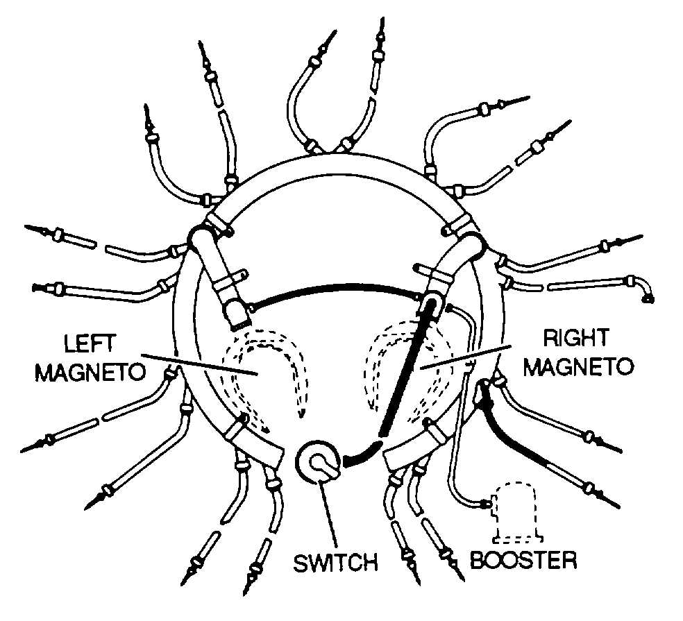
Ignition
harness.
The
ignition
harness, as shown in figure 7-18, contains an insulated
wire for each cylinder that the magneto serves In the
engine. One end of each wire Is connected to the
distributor block and the other end is connected to the
proper spark plug. The Ignition harness serves a dual
purpose. It supports the wires and protects them from
damage by engine heat, vibration, or weather. It also
serves as a conductor for stray magnetic fields that
surround the wires as they momentarily carry high-voltage
current. By conducting these magnetic lines of force to
the ground, the ignition harness cuts down electrical
interference with the aircraft radio and other electrically
sensitive equipment. When the radio and other electrical
equipment are protected in this manner, the ignition
harness wiring is said to be a shield. Without this
shielding, radio communication would become virtually
impossible. The ignition harness check consists of a
visual and an electrical check using the following
procedures.
(a)
Examine
all
accessible
parts
of
distributors, harnesses, and leads for chafing, broken
insulators,
corrosion,
moisture,
damaged
or
dirty
terminals, and security of mounting at the time specified
in the applicable maintenance manual.
Figure 7-18. Ignition Harness
(b)
Repair or replace defective parts as
necessary. Keep all parts clean and free of foreign
matter.
NOTE
The high-tension system manifold Is
never taken apart in the field, as this
will destroy the elastic gel seal.
1
Clean dirt and grease from harness
by wiping with a clean, dry cloth.
2
Clean
terminals
with
acetone,
Federal Specification O-A-51.
NOTE
Replace ignition harness leads when
more than three wire strands are
broken in one inch of harness length
or if Insulation is damaged
(c)
Perform a high-voltage breakdown
test when an ignition malfunction occurs and after cable
replacement in rewireable harness or leads. Use an
approved high-voltage tester, and test for serviceability as
follows.
1
Remove all leads from spark plugs.
2
Remove
spark
plug
elbow
assembly from ignition lead.
3
Examine
lead
insulation
for
evidence of chafing, breaks, or holes. Replace parts as
required.
4
Ground all leads, except one for
number 1 cylinder, to engine.
5
Connect ground lead of tester to
engine, and connect high-tension lead to number 1
cylinder lead.
6
Test
and
record
any
leakage
detected.
7
Test remaining leads.
8
When
two
leads
from
same
distributor show leakage, remove ground from both leads
and repeat test. When leakage is stopped by removing
ground from other lead, leakage is probably between.
7-19