TM 1-1500-204-23-2
(b) Installation precautions Install V-ring packing individually, making certain that packing is properly seated by
tapping lightly with a small, clean, well-rounded blunt rod or similar instrument. Do not use screwdriver or other sharp
tools. Do not Install rings in sets, that is, more than one ring at a time. V-ring packings must never be squeezed
excessively nor be loose in gland, but should be held firm to operate properly Packing should contact gland walls on both
inside and outside diameter.
4-8. Backup Rings. Backup rings are used to support O-rings and to prevent them from wearing, thus causing
leakage. Teflon backup rings are generally used with both packings and gaskets; however, leather backup rings may be
used with gasket type seals in systems operating up to 1,500 psi. Teflon rings are made from a fluorocarbon-resin
material which is tough and friction resistant and which is more durable than leather Backup rings made from Teflon do
not deteriorate with age, they are unaffected by any other system fluid or vapor, and they tolerate temperature extremes
greater than those encountered In high-pressure hydraulic systems Precautions similar to those applicable to O-rings
must be taken to avert contamination of backup rings and damage to hydraulic components.
a. Identification Backup rings are not color coded or otherwise marked and must be identified from package labels
The dash number, which follows the specification number on the package, shows the size, and In some cases relates
directly to the dash number, of the O-ring for which the backup ring is dimensionally suited. For example, the single
spiral Teflon ring MS28774-6 is used with the MS28775-006 O-ring and the double spiral Teflon ring MS28782-1 is used
with the AN6227B-1 O-ring
b. Installation. Care must be taken during handling and installation of backup rings. If possible, backup rings should
be put on by hand and without the use of sharp tools.
(1) Teflon backup rings Teflon backup rings must be Inspected before reuse and must be discarded If there is
evidence of compression damage, scratches, cuts, nicks, and fraying conditions.
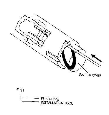
Figure 4-67. Internal O-Ring Installation(Paper Cover)
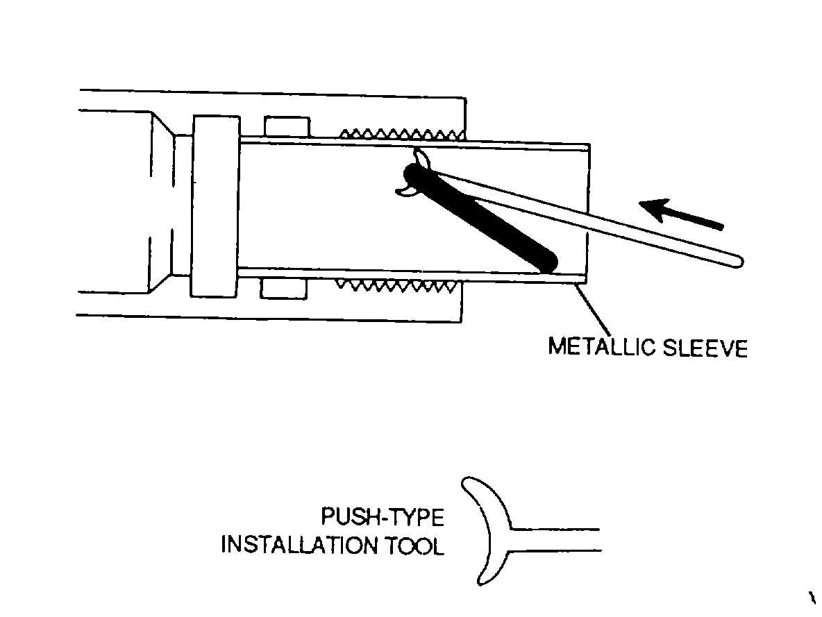
Figure 4-68. Internal O-Ring Installation (Metallic Sleeve)
4-84