TM 1-1500-204-23-2
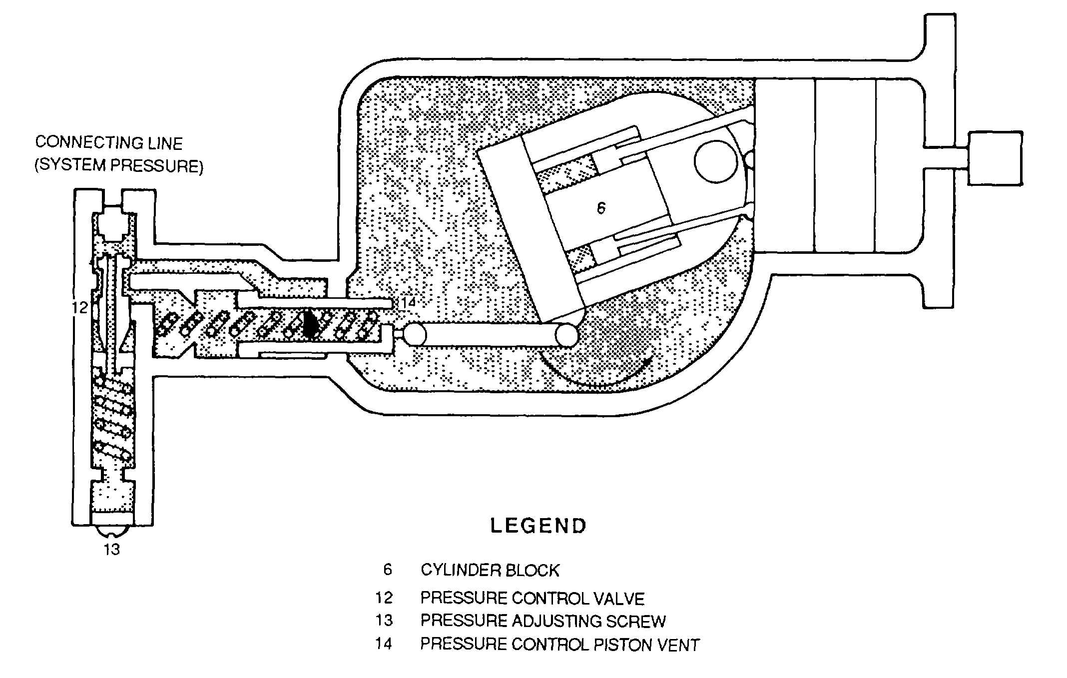
major component groups the rotating group and the pressure-compensating group. The rotating group consists of the
drive shaft (2), the cylinder barrel (4), nine pistons (3) with their piston shoes and locking plates (1) The pressure-
compensating group consists of a cam plate (6), a compensator valve (8), and a control piston (7). The cylinder barrel is
supported in the housing by a roller bearing (5). The drive shaft passes through but does not touch the inclined cam
plate to rotate the cylinder barrel unit. Pistons of the rotating group are actuated by tilting the non rotating cam plate The
contact is a universal action type, consisting of hydraulically balanced shoes and locking plates The length of piston
stroke is determined by the angle of the cam plate maximum pump output requires a high angle; zero pump output
requires a flat angle setting
1.
Full flow. In figure 4-109, the lower piston is shown near the beginning of the intake stroke. As the
cylinder unit is rotated, the piston moves to the left In its cylinder For nearly one-half of a revolution, the face port of this
cylinder is aligned with the annulus connected to the fluid inlet (10) Hydraulic fluid is sucked into the cylinder as the
piston in withdrawn just after passing the end of the inlet annulus. Further rotation forces the piston to the right and
aligns the cylinder with the annulus connected to the outlet port (9) and to the compensator valve (8). In this position,
fluid is forced from the piston. This discharge stroke lasts until the cylinder and piston reach the bottom position and are
ready to begin another intake stroke. At the same time, there are eight other pistons on the intake and discharge strokes,
all doing the same thing. Their pumping action continues until the fluid needs of the system are satisfied.
2. Zero flow. When a subsystem actuator completes Its travel, the need for pump output is reduced to zero
The pump senses the end of the actuator travel because the unused output causes a sudden increase in discharge
pressure As this pressure reaches the setting of the compensator valve, it pushes the valve to the right (see figure 4-110)
The pressure then pushes on to the control piston, causing It to move to the left and decreasing the angle of the cam
plate. This action decreases the effective length of the piston stroke, thus decreasing the volume of fluid delivered to the
system. In actual operation, the cam
Figure 4-108. Vickers Stroke Reduction Pump (Full Flow)
4-115