TM 1-1500-204-23-2
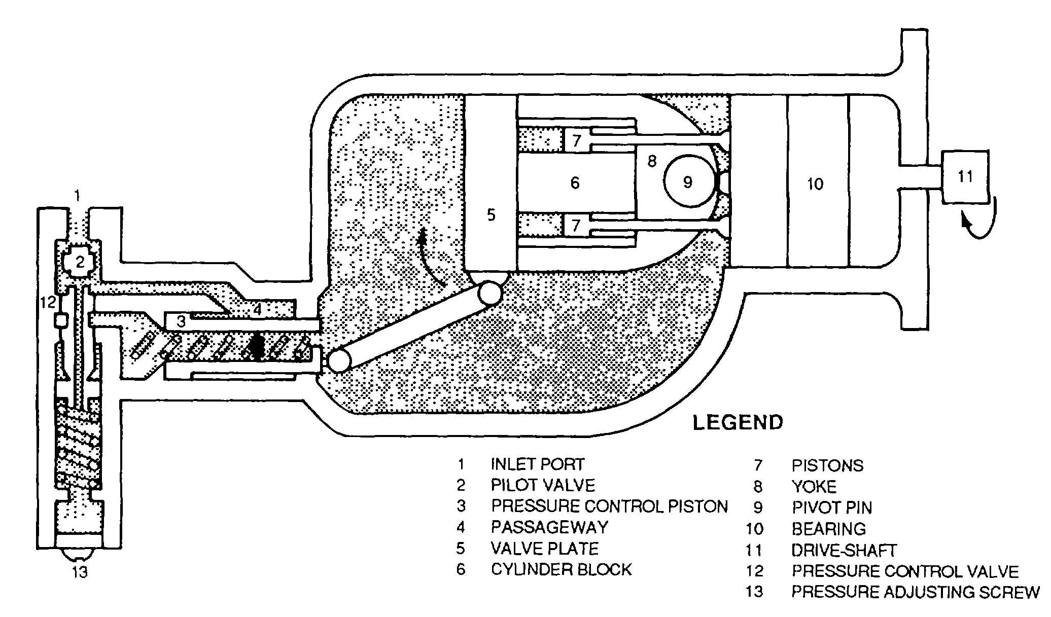
Figure 4-107. Vickers Stroke Reduction Pump (Zero Flow)
type pump The main difference between the two types Is the angle between the drive shaft and the cylinder block. In the
constant-volume pump, this angle is fixed; In the Vickers pump, the angle vanes automatically to satisfy the pressure-
volume demands of the system.
1 Zero Flow (See figure 4-107). In the stroke-reduction pump, the drive shaft (11), the pistons (7), and the
cylinder block (6) are all supported by the bearing (10) and they all rotate. A yoke (8) contains the cylinder block, which
swivels around the pivot pin (9). Before the pump builds up any pressure, the yoke Is held by the spring In the pressure
control piston (3) in the position shown In the full-flow illustration (see figure 4-106). When outlet pressure is at
maximum, the yoke is held in the position shown in figure 4-107. As long as there is no pressure in the system, the
cylinder block and yoke are In the extreme angle position. System pressure entering the connecting line (1) acts on the
pilot valve (2), pushing It down against the spring toward the zero flow position This opens the passageway (4), sending
pressure against the rod side of the pressure control piston (3). As the piston moves to the left, Its spring is compressed.
This force, which is transmitted through the valve plate (5), causes the yoke to swivel upward so that the cylinder block
moves toward a zero angle. If the cylinder block reaches the extreme zero flow point, there is no fluid output to the
system. This is because the pistons have no stroke in the cylinder block
They simply rotate with the cylinder block without moving back and forth
2 Full flow. As the pressure in the system starts to drop, Its force on the pilot valve is reduced. When this
happens, the spring under the pilot valve moves it upward. This reduces the opening to the passageway and cuts down
the pressure on the pressure control piston so that its spring pushes it to the right Now the yoke swivels downward,
causing the stroke of the pistons to increase The pressure and volume output again start to increase until the system's
demands are met (see figure 4-108). The action of the pressure control valve (12) stabilizes the position of the cylinder
block (6). Its angle adjusts to meet the system demands Notice that the hollow center of the pressure control piston Is
vented to the inside of the case (14) so that fluid trapped inside the piston can escape to the case. A foot valve (not
shown) prevents case pressure from becoming too high.
3
Pressure regulation. Pressure is Increased or decreased by turning the adjusting screw (13, figure 4-
108). An internal relief valve prevents damage in case the pressure control valve fails to function properly
(c) Kellogg stroke-reduction pump The Kellogg pump shown In figure 4-109, is made up of two
4-114