TM 1-1500-204-23-9
(1)
Insert the drill bit into the drill chuck.
(2)
Install an air hose to the air inlet
connection.
NOTE
A drill bit that wobbles or is slightly bent
should not be used because it will cause
enlarged holes.
(3)
Test the drill bit for trueness and vibration
by running the drill freely.
WARNING
Wear
eye
protection
when
drilling.
Failure to comply may result in serious
injury to personnel.
(4)
Always hold the drill at right angles to the
work regardless of the position or curvatures. Tilting the
drill at any time may cause elongation of the hole.
c.
Care. Consult the applicable operator's and
service manuals for inspection and maintenance
procedures for pneumatic drills.
5-8.
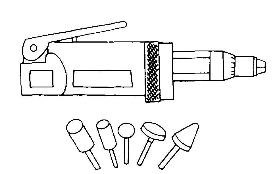
Pneumatic Grinder. A pneumatic grinder is
used where electrical power is not available or where
sparks from an electric motor could be a fire hazard.
a.
Types. A typical pneumatic grinder is shown in
figure 5-16. The grinders are rated by no-load speeds,
which typically result in terms of light-, medium-, and
heavy-duty loads being used to describe the grinder.
The grinding stones come in numerous shapes and give
versatility to the grinder.
Figure 5-16. Pneumatic Grinder
b.
Use. Procedures for using pneumatic grinders
are as follows:
(1)
Insert the grinding stone into the chuck.
(2)
Install an air hose to the air inlet
connector.
NOTE
A grinding stone that wobbles or has a
bent shaft should not he used.
(3)
Test the grinding stone for trueness and
vibration by running the grinder freely. Grinding stones
which are glazed, out of true or out of round may be
reshaped with a dressing stick.
WARNING
Wear eye protection when grinding.
Failure to comply may result in serious
injury to personnel.
(4)
Perform grinding operations by holding
the grinder so that the proper edge of the grinding stone
is against the work.
c.
Care. Consult the applicable operator's and
service manuals for inspection and maintenance
requirements.
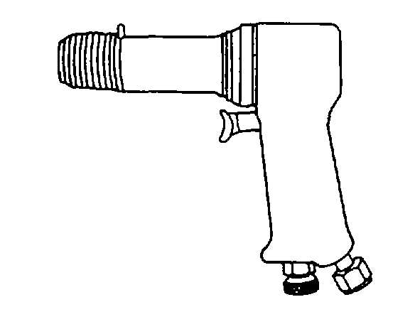
5-9.
Pneumatic Hammer. The pneumatic hammer,
shown in figure 5-17, is used for heavy-duty cutting,
shearing, punching, and chiseling and breaking joints.
The built-in air regulator varies speed and power.
Pneumatic hammers have strokes varying from 1 1/2 to
3 1/2 inches, at 2,000 to 4,500 blows per minute. This
hammer uses insertable chisels with different end
shapes, such as tapered punch, panel cutter, cut-off,
and weld buster.
Figure 5-17. Pneumatic Hammer
5-8