TM 1-1500-204-23-9
7-14 Change 4
h.
If the safety cable does touch the wall of the
fixture, the tool should not be returned to service, and
must be adjusted or serviced. Follow the instructions in
the next section of this manual.
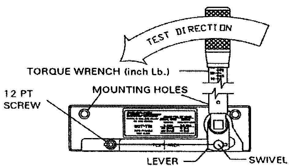
Figure 7-26. Torque Verification
Fixture and Torque Wrench
i.
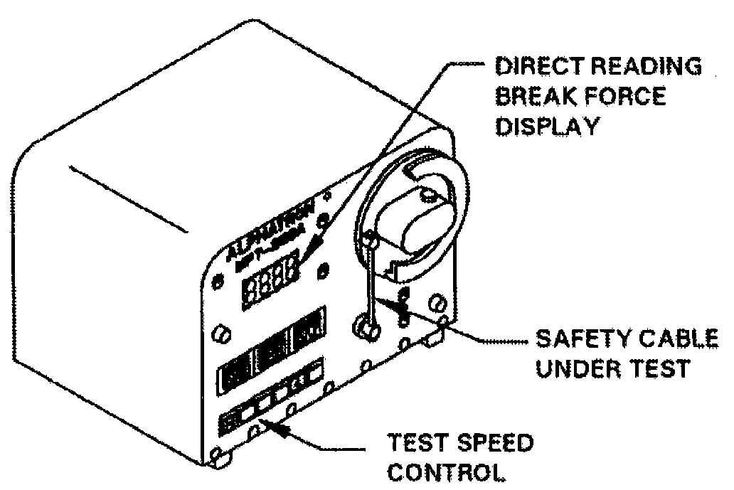
Tool calibration verification with an electronic
tester. It may be required in some applications to use an
electronic pull tester to test safety cable to destruction. If
this is required, the tester (Figure 7-27) should have digi-
tal readout capability, and a two (2) inch/minute pull rate.
Figure 7-27. Electronic Safety Cable
Pull Tester
j.
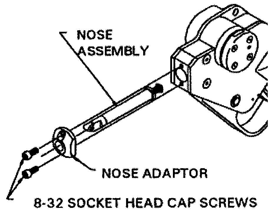
Safety Cable tool Indenter Adjustment/Calibra-
tion. Remove the nose assembly by removing the two
8-32 socket head cap screws with a 9/64 inch hex wrench
(see Figure 7-28).
Figure 7-28. Removal of Safety Cable
Tool Nose Assembly
k.
Unlock the jamnut using the SCT32084 tool
(supplied by the manufacturer). Adjust the pushrod
adjustment screw using a 1/4 inch straight edge screw-
driver (see Figure 7-29). Turn the screw clockwise to
loosen the crimp (enlarge the gaging dimension), or
counterclockwise to tighten the crimp (reduce the gaging
dimension). After each adjustment, securely tighten the
jam nut using the SCT32084 tool (while holding the
adjustment screw tight with the screwdriver). Reinstall
the tool nose being sure to tighten the 8-32 socket cap
screws securely.
CAUTION
Do not adjust the pushrod
adjustment screw more than
one quarter turn at a time. Radi-
cal adjustments may cause
damage to the tool.
l.
Retest the tool using the procedures previously
defined. Accept or reject the tool on the basis of the
pass/fail criteria stated above, and repeat adjustment
process if necessary to achieve passing results.