TM 1-1500-204-23-9
for engine thrust nuts, propeller nuts, and helicopter
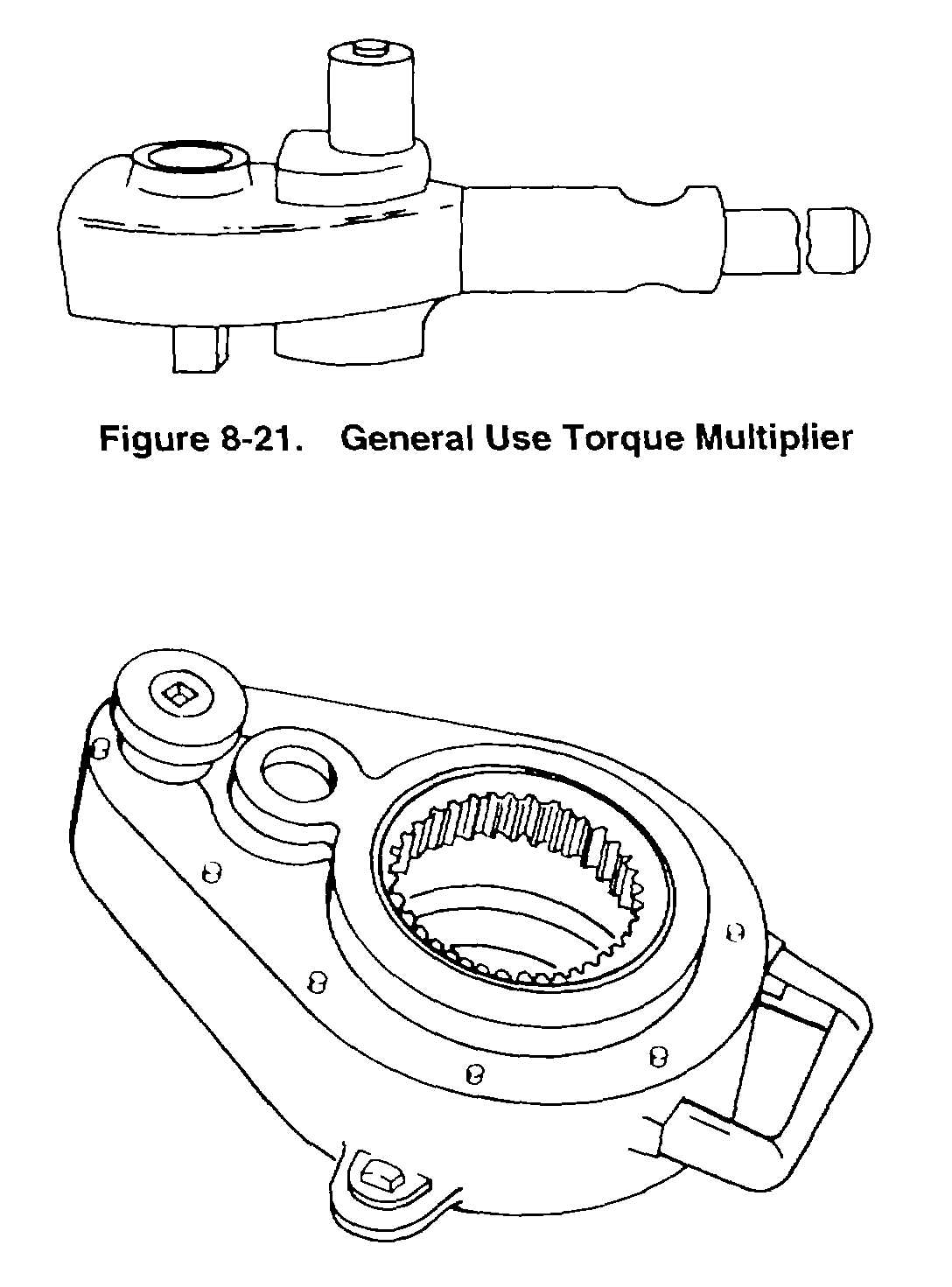
rotor hub nuts. Figure 8-21 and 8-22 show typical
torque multipliers.
a. Use. Torque multipliers are available in ratios
ranging from 3:1 to 11.1:1. Multipliers must be
anchored or secured to a structure relative to the
fastener being tightened, or be fitted with a reaction bar
to prevent the multiplier from turning. For this reason,
their use is usually restricted to special applications.
b. Determining Torque. When using a torque
multiplier, the torque to be applied with the torque
wrench is determined by dividing the specified torque for
the fastener by the multiplier ratio. For example: If the
torque specified for the fastener is 3000 foot-pounds and
a torque multiplier with an 11.1 to 1 ratio is going to be
3000
used, then 11.1 or 270-pounds is the torque applied by
the torque wrench. In this case, a 350 foot-pound
capacity torque wrench or a wrench up to a 900 foot-
pound capacity would be used to apply 270 foot-pounds
of torque to the input of the torque multiplier. In this
range
Figure 8-22. Hub Nut Torque Multiplier
of torque wrenches, the applied torque is between the
desired 30- to 80-percent range.
8-10. Torque Multiplier Power Wrench. Utilizing a
powerful gear train, the torque multiplier power wrench,
shown in figure 8-23, is completely mechanical in its
operation. This tool operates on the same principle as
the general purpose torque multipliers described in
paragraph 8-9. The wrench is operated by turning a
small hand crank, but power tools (including air or
electric drills, nut runners, etc.), may be used for
speedier operation. A balanced features of the drive
gearing prevents snap-back should the input crank be
released.
a. Description. Output torque of the torque multiplier
power wrench, can be read directly. The torque
indicator is calibrated in foot-pounds or inch-pounds.
The operator can also read degree-of-turn on a
protractor on the input face of the unit. Wrench output
is a standard size square female drive. A ratchet
assembly controls the direction of rotation and provides
for quick take up and alignment. Counter torque is
absorbed by two pins located on the back of the wrench.
This reaction force is transferred to the load cells and
then to the gauge for direct output torque reading.
b. Use. As a general rule, always turn the input
handle in the direction that the output drive must turn.
Refer to the applicable aircraft maintenance manual for
specific uses for this tool.
NOTE
Do not use impact wrenches of any kind
to operate this wrench.
8-11. Torque Procedures Without a Torque Wrench.
In certain instances, when a torque wrench is not
available,
the
aircraft
maintenance
manual
may
prescribe an alternate method for determining that a
fastener is properly torqued. The two methods which
are commonly used are the wrench-arc method of
tightening, and the use of preload-indicating washers.
a. Wrench-Arc Method of Tightening. The wrench-arc
method of tightening will be used only when specified in
applicable aircraft maintenance manuals.
(1) Preliminary steps. The following paragraphs
provide preliminary steps that must be accomplished
before performing this operation:
Figure 8-21. General Use Torque Multiplier
8-10