TM 1-1500-204-23-9
Table 3-2. Snap Gauge Tolerances
To and
Above
Including
X1
Y2
Z3
0.029
0.825
0.00004
0.00007
0.00010
0.825
1.510
0.00006
0.00009
0.00012
1.510
2.510
0.00008
0.00012
0.00016
2.510
4.510
0.00010
0.00015
0.00020
4.510
6.510
0.00013
0.00019
0.00025
6.510
9.010
0.00016
0.00024
0.00032
9.010
12.010
0.00020
0.00030
0.00040
1
Precision lapped
2
Lapped
3
Ground or polished (grinding marks may be in evidence)
(a)
Clamp the snap gauge in a vise
or a holder.
CAUTION
To prevent damage to the gauge from the
jaws of the vise, cover the jaws of the
vise with blocks of wood or sheets of soft
metal, such as brass.
NOTE
This procedure describes adjusting the
GO dimension first; however, either the
GO or the NO GO dimension may be
adjusted first.
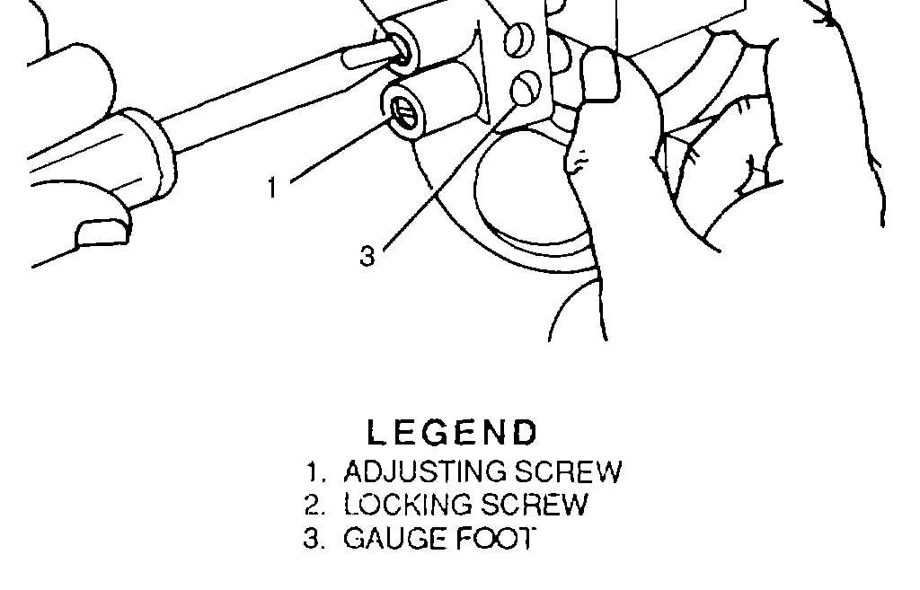
(b)
As shown in figure 3-65, turn
the locking screw (2) and turn the adjusting screws (1)
until the dimension is set (3).
NOTE
The desired dimension may be taken
from a master disc, a precision gauge
block, or a master plug.
(c)
Turn the other adjusting screw
until the NO GO dimension is set.
(d)
Tighten the locking screws with
the master precision piece still in place.
(e)
Remove the master precision
piece.
(f)
Recheck the gauge to make
sure the dimensions have not changed before using the
gauge.
LEGEND
1. ADJUSTING
2. LOCKINGSCREW
3. GAUGEFOOT
Figure 3-65. Adjusting the Snap Gauge
3-30