TM 1-1500-204-23-9
(a)
Find the slot that refuses to
pass the wire without forcing.
(b)
Try the next larger slots until
one is found that passes the wire. This is the correct
size.
NOTE
·
Measurements are taken at the slot portion
rather than the cutout portion of the gauge.
·
The decimal equivalent of the gauge
number is shown on the opposite side of the gauge.
c.
Care. Observe the following practices for
the care and upkeep of sheet metal and wire gauges:
(1)
Coat metal parts of wire gauges with a
light coat of oil to prevent rust.
(2)
Store gauges in separate containers.
(3)
Keep graduations and markings clean
and legible.
(4)
Do not drop wire gauges. Small nicks
and scratches will result in inaccurate measurements.
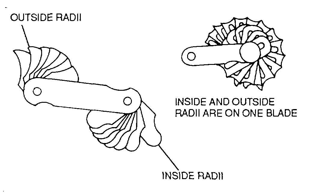
3-19. Fillet and Radius Gauges. Fillet and radius
gauges are used to check the inside or outside corners
(or fillets) of a machined part.
a.
Description. The blades of fillet and radius
gauges are made of hard-rolled steel. The double
ended blades of the gauge have a lock which holds the
blades in position. The inside and outside radii are on
one blade on one of the gauges shown in figure 3-73.
The other gauge has separate blades for inside and
outside measurements. Each blade of each gauge is
marked in 64ths. Each gauge has 16 blades.
b.
Use. Fillet or radius gauges are used to
check the inside or outside corners of a machined part,
as shown in figure 3-74. These gauges can be used in
any position and at any angle for both inside and outside
radii.
c.
Care. Observe the following practices for
the care and upkeep of fillet and radius gauges:
Figure 3-73. Fillet and Radius Gauges
(1)
Coat metal parts of fillet and radius
gauges with a light film of oil to prevent rust.
(2)
Store gauges in separate containers.
(3)
Keep graduations and markings clean
and legible.
(4)
Do not drop fillet and radius gauges.
Small nicks and scratches will result in inaccurate
measurements.
3-20. Dial Indicators. A dial indicator is a precision
measuring tool designed for checking items such as
bearing radial and axial play, propeller shaft run out,
bushing and flight control system components for
excessive play. The dial indicator plays an important
part in deciding if a part is worn beyond an allowable
tolerance.
a.
Description. The dial indicator consists of a
dial with reading needle and a graduated scale. The dial
indicator has a measuring range from 0.001 to 0.200 of
an inch. The dial is adjustable and has the reading
pointer located on the back of the dial. The indicator
can be mounted in various positions using a special
clamp and tool post holder which is provided in the dial
indicator kit. This assembly is shown in figure 3-75.
b.
Use. Generally speaking, the dial indicator
measures variations from a perfectly circular condition.
Proceed with installation and use as follows:
3-34