TM 1-1500-204-23-9
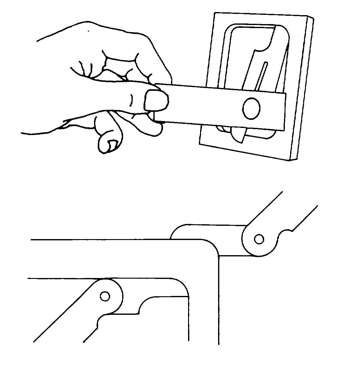
Figure 3-74. Using Fillet and Radius Gauges
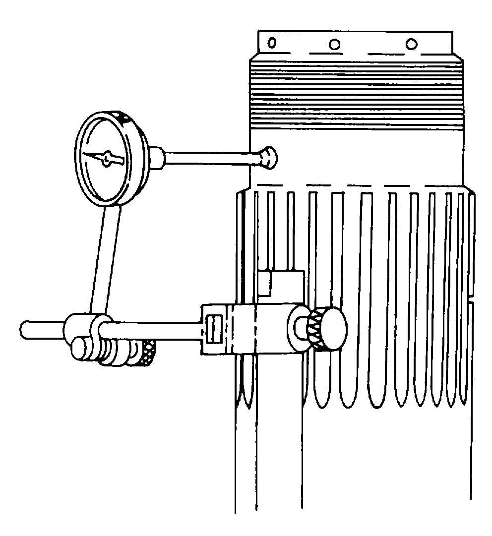
Figure 3-75. Dial Indicator Installed on Propeller
Shaft
NOTE
The following general procedures are used or checking propeller shaft runout. Refer to the applicable
aircraft maintenance manual for specific procedures to be used when use of a dial indicator is required.
(1)
Remove propeller.
(2)
Remove one of the nuts securing thrust bearing cap to reduction gear assembly and install a reversible
type dial indicator on the long stud from which the nut was removed (see figure 3-76).
(3)
Adjust dial indicator so that arm point is on propeller shaft at front cone location.
(4)
Rotate propeller shaft and note total indicator movement. The maximum allowable runout at front
cone location is found in the applicable aircraft maintenance manual.
(5)
Adjust dial indicator so that arm point is on propeller shaft rear cone location.
(6)
Rotate propeller shaft and note total indicator movement. The maximum allowable runout at rear cone
location is found in the applicable aircraft maintenance manual.
c.
Care The dial indicator is a delicate measuring instrument and must be treated as such. Exercise care when
handling so that it is not damaged, as this may result in inaccurate measurements.
3-21. Telescoping Gauges. Telescoping gauges, shown in figure 3-77, are used for measuring the inside size of slots
or holes up to 6 inches in width or diameter. They are T-shaped tools in which the shaft of the T is used as a handle, and
the crossarm used for measuring. The crossarms telescope into each other and are held out by a light spring.
a.
Selection. These tools are commonly furnished in sets, the smallest gauge for measuring the distances from
5/16 to 1/2 inch, and the largest for distances from 3 1/2 to 6 inches.
3-35