
NAVAIR 01-1A-505-2
004 02
TO 00-25-255-1
Page 21
TM 1-1500-323-24-2
Figure 14. Locking Contacts
Figure 15. Unlocking Contact Retention
Mechanism of Socket Contact
CAUTION
Inspect tool tips for damage such as nicks,
burrs, or distortion before use. Failure to do so
may damage the wire or connector.
a. If not previously removed, remove backshell
from rear of connector (WP 004 03). Turn rear nut
assembly counterclockwise until slight resistance is felt
(2 1/2 turns or 5/64 inch space, minimum). Yellow stripe
will be visible (Figure 10).
b. Select removal tool specified in applicable
contact tooling table (Tables 5, 6, 8 or 9).
c.
Remove sealing plug, if installed.
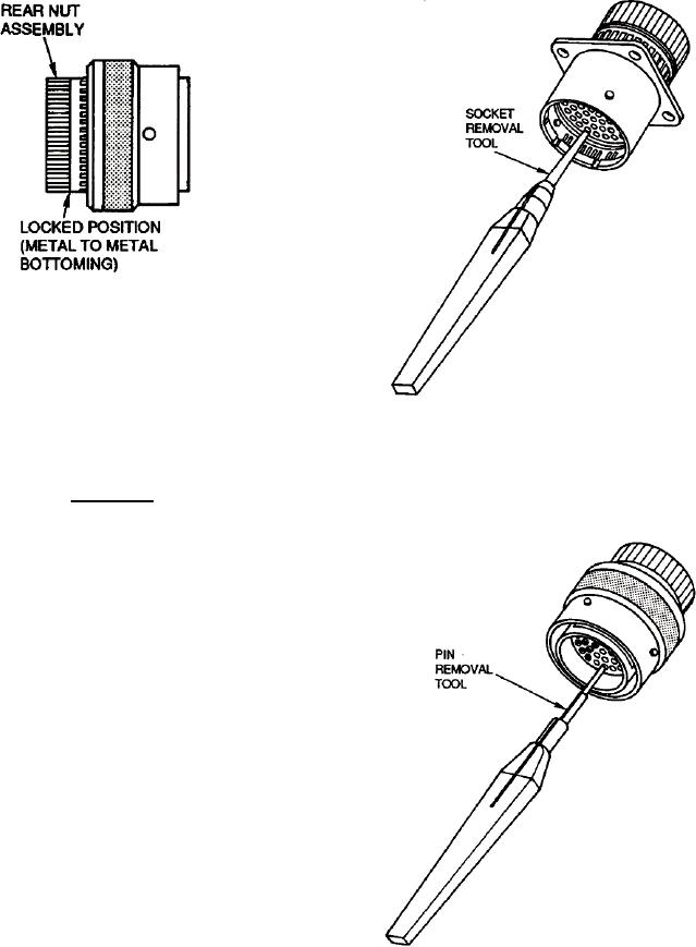
d. To remove socket contacts, insert tool through
insert and into socket contact (Figure 15).
e.
To remove pin contacts, align and place tool
over exposed pin (Figure 16).
Figure 16. Unlocking Contact Retention
Mechanism of Pin Contact