
NAVAIR 01-1A-505-2
004 02
TO 00-25-255-1
Page 23
TM 1-1500-323-24-2
When using a heat tool, do not use electrical
power from the aircraft being repaired. Use
electrical power from a ground power unit.
Use of nitrogen with the HT-900B/HT-920B
heat gun in an enclosed area can be hazardous.
Discharge of nitrogen into a poorly ventilated
area can result in asphyxiation.
CAUTION
Do not use electrical power from aircraft being
Figure 18. MIL-C-81511 Series 3 Typical Connector
repaired. Use electrical power from ground
power unit.
Be careful if using metal tools (M81969). These
tools can damage the wire sealing grommet in
the connector. Plastic tools are preferred.
Inspect tool tips for damage such as nicks,
burrs, or distortion before use. Damage to the
connector wire sealing grommet can occur.
Avoid using metal tooling to remove and install
backshells. These tools can damage the
backshell and connector. Non-metallic tools
are designed to wear before damaging
connector or backshell.
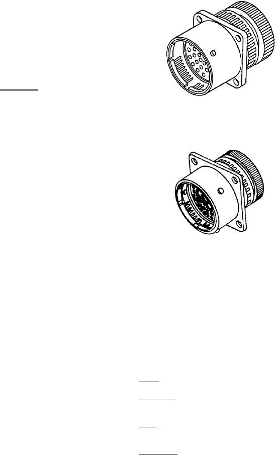
Figure 19. MIL-C-81511 Series 4 Typical Connector
Do not remove a contact attached to a broken
wire with an unwired contact removal tool.
The tool and connector may be damaged,
and RFI signals. Configurations available under Series
Wire strands may be encountered at any point
3 and 4 are identified in Figure 20, along with the
up to 5/16 inch of tool insertion. Do not force tool
corresponding specification sheets and part number
if wire strands are encountered.
breakdown.
Withdraw tool any time it cannot be advanced
52. PART NUMBER. The part number contains the
into connector. Inspect tool tip for nicks, cracks,
information necessary for the proper selection and
mushrooming, and other damage that will
procurement (Figure 20) and includes the following:
prevent proper functioning. Replace removal
tool and repeat procedure if required.
53. Prefix. The prefix denotes the military specification.
51. Series 3 and 4 (Figure 18 and 19) are available in
54. Shell Style. The shell style denotes the type and
two shell styles: a long shell version (Series 3),
mounting to the connector.
commonly called 100% scoop-proof, and a short shell
version (Series 4), commonly called 50% scoop-proof.
55. Class. The class indicates the environment resisting
The long shell version will prevent scooping damage
abilities along with mounting type.
with pins installed in either the plug or receptacle. The
short version will prevent scooping damage provided
56. Shell Size. The shell size is indicated by a
the pin contacts are installed in the receptacle half of
progressive lettering system .
the connector. Receptacles contain the grounding
spring members used to ground both direct current