NAVAIR 01-1A-505-2
011 02
TO 00-25-255-1
Page 13
TM 1-1500-323-24-2
79. Contact Availability. Crimp contacts are supplied
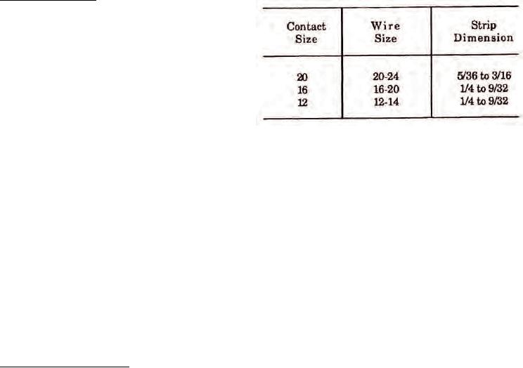
Table 6. Strip Dimensions
with each connector unit package and consist of a full
complement plus one spare per size for connectors of
26 contacts or less. Connectors with more than 26
contacts will have two spares of each size used. Contacts
may also be ordered in individual quantities when
necessary.
80. CONTACT APPLICATION. Contacts used in
NAS1599 connectors are manufactured in accordance
with NAS1662 for pin contacts and NAS1663 for socket
88. CONTACT CRIMPING. See NAVAIR 01-1A-505-1,
contacts. The part number breakdown is illustrated
WP 013 00. Crimp contact in accordance with following
(Figure 5).
procedure:
81. POWER CONTACTS. Power contacts are used to
a.
Select correct crimp tool (Table 4).
connect single conductor wire through connectors.
The power contacts range from size 16 through 20 for
b. Perform die closure check, install positioner,
these connectors. Socket and pin contact part numbers
and set selector knob for gage of wire.
are listed along with colorbands (Table 3).
c.
Insert stripped wire into contact conductor
82. TOOLING. Select the proper tooling for the specific
barrel. Ensure all wire strands are inside contact
contact part number (Table 4) and refer to NAVAIR 01-
conductor barrel and visible in contact inspection hole.
1A-505-1, WP 013 00 for the proper assembly
procedures.
d. If insulation gap is too large, trim conductor as
required. If insulation gap is too small, trim insulation
83. BACKSHELL REMOVAL AND INSTALLATION.
as required,
For backshell removal and installation refer to
WP 011 03.
e.
Crimp contact to wire.
84. CONNECTOR BUILD-UP.
89. CONTACT INSERTION. Insert wired or unwired
contacts in accordance with following procedure:
85. The build-up procedures for both threaded coupled
and bayonet coupled NAS1599 connectors are the same,
a. Remove sealing plug and/or contact from
however the connector contact cavities for threaded
contact cavity (Paragraph 93).
coupled connectors are identified by numbers while
bayonet coupled connectors have contact cavities
b. Ensure wire or cable on contact is routed
identified by letters.
through connector backshell.
86. WIRE DIAMETER BUILD-UP. If wire outside
c.
Select correct insertion tool (Table 4).
diameter is not large enough to fill wire sealing grommet
holes, build up wire outside diameter by applying
d. Place wire and contact assembly into colored
heat-shrinkable insulating sleeving. This must be
tip of insertion tool (Figure 10). Ensure tool tip is over
accomplished prior to contact insertion.
conductor barrel and butted against contact shoulder.
87. WIRE STRIPPING. Strip wire in accordance with
e.
Insert tip of contact into cavity. Start contact
following procedure:
insertion near connector center cavities and work
outward.
a. Cut wire to proper length. Ensure enough wire
remains for adequate strain relief without leaving excess
f.
Axially align contact with contact cavity.
slack.
g. With firm and even pressure, press tool against
b. Strip insulation to the proper dimensions
contact shoulder and seat contact into cavity
(Table 6), using proper stripping procedures (NAVAIR
(Figure 11). A slight click may be heard as retention
01-1A-505-1, WP 009 00). Select contact (Table 3).
tines snap into place behind contact shoulder.

