
NAVAIR 01-1A-505-3
TO 1-1A-14-3
TM 1-1500-323-24-3
003 02
1 September 2011
Page 38
NOTE
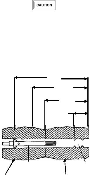
Refer to figure 26 for approximate dimensions of
a size 22 contact and cavity.
Wire strands may be encountered at any point up
to 5/16 inch of tool insertion. It is important not
The dimensions in this procedure are based on a
to jam any strands of wire up to his point.
size 22 contact.
Withdraw removal tool anytime during insertion
c. Gently insert removal tool into cavity in about
when it cannot be advanced into connector using
1/16 inch units, releasing tool after each unit if resistance
these procedures. Inspect tool tip for nicks,
is felt.
cracks, mushrooming, and other damage that will
NOTE
prevent is functioning. Replace removal tool and
repeat procedure, if required.
Rotating removal tool works splayed wire
strands into slot of tool, allowing tool to pass.
1/2 Inch
Removal tool may be blocked at rear of
3/8 Inch
contact by plastic insert or additional strands
of broken wire.
5/16 Inch
d. If resistance is felt before removal tool reaches
back end of contact, withdraw tool slightly, rotate about
l/6 of a turn, and reinsert tool. Repeat rotating and
1/8 Inch
insertion procedure until tool passes with minimum
additional force to 5/16-inch depth back end of contact
(Figure 26 and 27).
e. Wiggle removal tool gently to help it into insert
bore and over back of contact. Additional rotation may
be required if broken strands are encountered.
f. Continue insertion of removal tool until positive
stop is felt at about 1/2 inch depth.
Seal Area
Contact Wire Barrel
g. Exert axial pressure on engaging end of contact,
Plastic Retaining Insert
Resilient Rear Insert
using appropriate pin or socket as pusher. (If contact
does not move, seat removal tool more firmly).
Figure 26. Typical Connector Dimensions
h. Push contact completely out rear of connector
before disengaging removal tool (Figure 28).