NAVAIR 01-1A-505-3
TO 1-1A-14-3
TM 1-1500-323-24-3
014 02
1 September 2011
Page 53/(54 Blank)
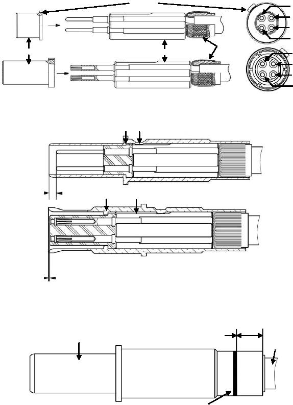
10. Slide spacer over contacts till butted against cable shield.
11. Slide insulator over contacts till butted against spacer. Ensure polarizing keys are aligned.
ENGAGING FACE
Polarizing
Pin 1 RX(+)
Pin 4TX(-)
Pin
Contact
Pin 3 RX(-)
Pin 2TX(+)
CableShield
Insulator
Spacer
Pin 4TX(-)
Socket
Pin 1 RX(+)
Contact
Pin 2TX(+)
Pin 3 RX(-)
12. Slide outer contact body over inner contact sub-assembly till fully seated. Ensure polarizing keys a
matched.
Polarizing Keys
Pin
Quadraxial
Contact
0.035"
Polarizing Keys
0.9 mm
Socket
Quadraxial
Contact
0.016"
0.4 mm
13. Crimp outer contact body in the designated area using tools in Table 6 and NAVAIR 01-1A-505-
1, WP 013 00.
Designated
Outer Contact
Crimp Area
Cable
Black Band
Figure 43. 620175050, 620075050,617175051 and 617075051 Quadraxial Contact Buildup (Sheet 2)

