NAVAIR 01-1A-505-3
TO 1-1A-14-3
TM 1-1500-323-24-3
014 02
1 September 2011
Page 49
14. Insert intermediate contact sub-assembly into the outer contact insulator and outer contact sub-
assembly.
15. Push on the outer contact, outer ferrule and cable to ensure all components are seated.
Outer
2nd Shield
Outer
Contact
Ferrule
Contact
Ferrule
Push in on Cable
while crimping.
Outer Contact
Crimp Area
0.145"
3.7 mm
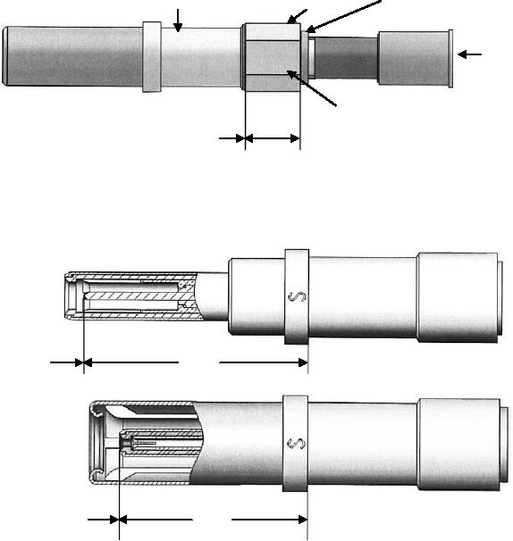
16. Crimp the outer contact in the area indicated below using tools in Table 5 and NAVAIR 01-1A-505-1, WP
013 00. Continue to maintain inward pressure on cable while crimping to ensure all parts a properly seated.
17. After crimping inspect for correct dimensions.
Pin
Triaxial
Contact
After
0.435"
Crimping
11 mm
Dimension
Socket
Triaxial
Contact
After
0.355"
Crimping
9 mm
Dimension
Figure 41. 617190014 and 617090014 Triaxial Contact Buildup (Sheet 3)

