
NAVAIR 01-1A-505-3
TO 1-1A-14-3
TM 1-1500-323-24-3
014 03
1 September 2011
Page 14
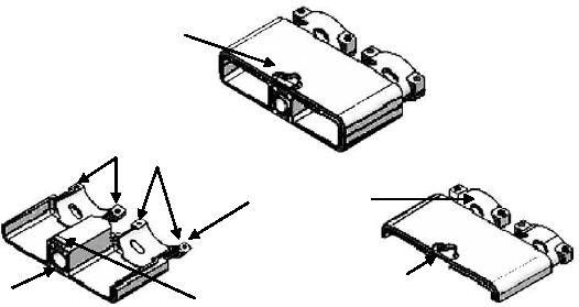
Assembled
Backshell
Backshell Screws
(4 Screws)
Harness Clamp
Connector
Lower Hinge
Mounting
Upper Hinge
Jackscrew
Lower Backshell Half
Upper Backshell Half
Figure 19. 527401 EMI Backshell Assembly
CAUTION
Install a minimum of one overlapping layer of MIL-I-22444C tape
between the wire bundle and the saddle clamp.
Install adequate tape to assure a snug fit, but without preventing the
grip halves from bottoming out against each other.
e. Build up wire bundles by using MIL-I-22444C tape. E nsure the tape provides a snug, abrasion protective fit
between the wire bundle and the saddle clamp grip halves.
f. Center the tape under the grip halves. If difficulty is experienced in wrapping the tape between the saddle clamp
halves, the tape may be wrapped where the bundle is clear of the arms and then the wrap slipped into position between
the arms. Flush the wrap edges +/- 1/32 inch top and bottom. Do not allow wrap to spiral. See Figure 16.
g. Remove temporary tape and fold shields over tie string (toward the connector). See Figure 20.
h. Attach the lower half of backshell to the upper half hinge. Rotate the lower hinge up and secure to upper half
using four screws.