TM 1-1510-262-10
1.
11.
Fuel Control Unit
Prop Shaft
2.
Fuel control Unit Interconnect Rod
12.
Tach Generator (Prop N2)
3.
Fuel Pump
13.
Chip Detector
4.
14.
Prop Interconnect Linkage (Aft)
Oil Pressure Transfer Tube
5.
15.
Spark Igniter Plug
6.
Engine Mount Isolator
16.
Fuel Flow Divider
7.
Fireseal
17.
Engine Mount Isolator Bolt
8.
Trim Thermocouple
18.
Oil-to-Fuel Heat Exchanger
9.
19.
Rudder Boost Sensor
10.
20.
Engine Truss Mounting Bolt
Prop Interconnect Linkage (Fore)
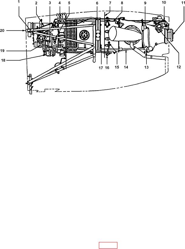
Figure 2-18. PT6A-67 Engine Right Side
b. Engine Air Inlet Anti-Ice System.
(1) Description. A small duct, facing into the exhaust low of the engine s left exhaust stack, diverts a
small portion of the engine exhaust gases to the engine air inlet lip. The gases are circulated through the engine air
inlet lip and then exhausted through a duct to the engine s right exhaust stack. The continuous low of hot engine
exhaust gases heats the engine air inlet lip, preventing the formation of ice. Two switches, placarded ENG INLET
LIP HEAT #1 and #2 (located on the overhead control panel, Fig. 2-13), operate solenoid valves in the lip heat
exhaust plumbing. These valves control the low of hot exhaust gasses to the inlet air lip assemblies.
(2) Fuel heater. An oil-to-fuel heat exchanger, located in the engine accessory case, operates continu-
ously and automatically to heat the fuel suficiently to prevent ice from collecting in the fuel control unit. Each fuel
control unit is also protected against ice. Fuel control heat is automatically provided during all engine operations.

