
TM 1-1510-262-10
2-25. ENGINE FIRE DETECTION SYSTEM.
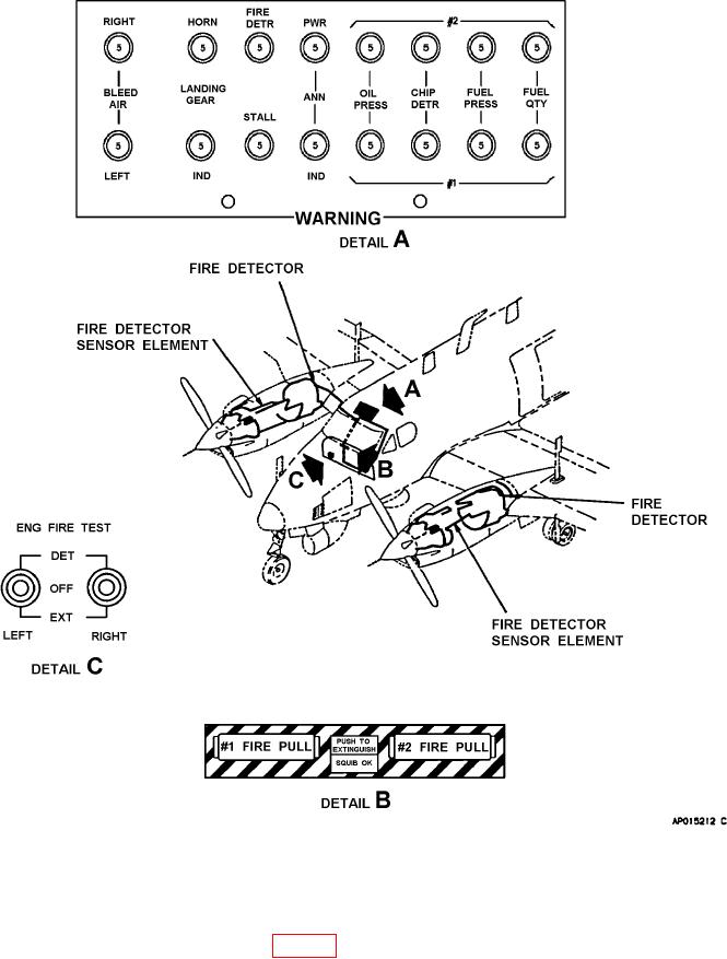
Figure 2-20. Engine Fire Detection System
a. Description. A ire detection system is installed to provide an immediate warning in the event of a ire or
over temperature in the engine compartment (Fig. 2-20). The main element of the system is temperature-sensing
tubing, routed continuously throughout the engine compartment terminating in a responder unit. The responder unit
is mounted in the accessory area on the upper left hand engine mount truss, just forward of the engine irewall.
The responder unit contains two sets of contacts: a set of integrity switch contacts, for continuity test functions of
the ire detection circuitry; and a set of alarm switch contacts, which complete the circuit to activate the ire warning
2-30