
TM 1-1510-262-10
Table 4-1.
Annunciator Panel Controls and Indicators -- Continued
Index #
Control/Indicator
Function
46
ANT STEERING Rotary Switch Selects one of the following:
AUTO Steering controlled automatically by IADL equipment.
MANUAL Steering controlled manually by antenna steering
azimuth control (item 45)
GROUND Steering controlled manually by GGB or AGE van
operator via IADL microwave link.
47
ANT AZIMUTH LED Display
Provides numeric display of IADL antenna azimuth in degrees,
with resolution to 0.1 degree. IADL antenna azimuth is relative
to aircraft orientation (i.e., 000.0 = nose, 90.0 = starboard,
180.0 = tail, 270.0 = port).
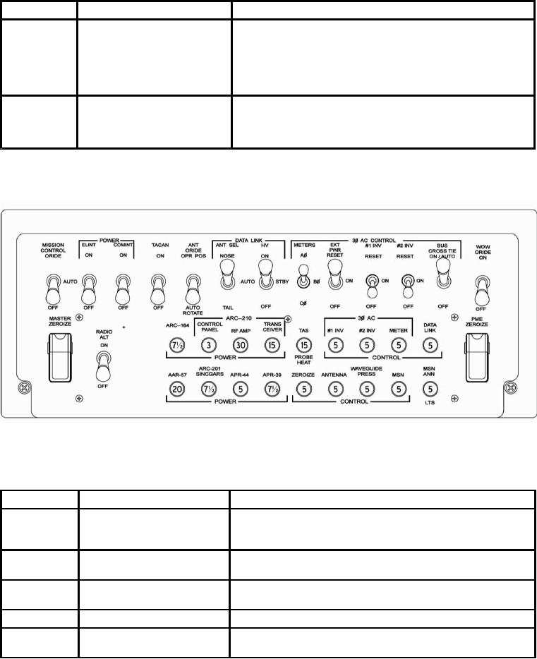
c. Mission Control Panel Controls, Indicators, and Functions.
Figure 4-3. Mission Control Panel
Table 4-2.
Mission Control Panel Controls and Indicators.
Index #
Control/Indicator
Function
48
MISSION CONTROL ORIDE
AUTO: Indicates the landing gear interlocks have been
Switch
overridden and power applied to the PME.
OFF: Normal Position
49
PWR ELINT Switch
ON/OFF: Applies/Removes DC Power to the PME
ELINT equipment
50
PWR COMINT Switch
ON/OFF: Applies/Removes DC Power to the PME
COMINT equipment
51
TACAN Switch
ON/OFF: Applies/Removes DC Power to the TACAN receiver
52
ANT ORIDE Switch
OPR POS: Allows for manual steering of tail boom antenna
AUTO ROTATE: Places tail boom antenna in auto rotation mode
4-5
Change 1