
TM 10-4930-351-14
0101 00
DISASSEMBLY-Continued
3
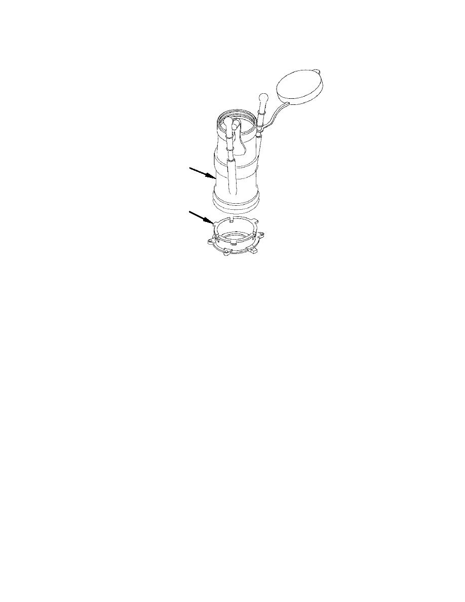
ADAPTER
Figure 2. Adapter
10. Remove three lock pins (figure 1, 14), three lock pin springs (15), three index pins (16) and O-ring (17). Discard O-ring.
NOTE
Do not remove plugs unless a leak has been observed.
11. Remove two plugs (figure 1, 18).
NOTE
Observe the orientation of the cam plate with respect to lever so that it can be duplicated
during reassembly. Mis-orientation will result in not being able to close nozzle properly.
12. Remove screw (figure 1, 19), washer (20) and O-ring (21) from the center of the lever (7). Discard screw (19) and O-
ring (21).
13. Remove lever (figure 1, 7) from nozzle body (6).
14. Remove and discard O-ring (figure 1, 22) and backup ring (23) from lever (7).
NOTE
Crank pin will be loose and can fall out when removing link assembly.
15. Remove assembled shaft (figure 1, 10), pin (24), link (25) and cam plate (26) from fuel nozzle body (6).
16. Remove cotter pin (figure 1, 27), nut (28), screw (29), pin (24), and washers (30). Discard cotter pin (27) and washers
(30).
17. Use needle nose pliers to remove continuity clip (figure 1, 31) if it is to be replaced.
0101 00-3
