
TM 55-1510-215-10
The copilot's turn and bank is pneumatically operated.
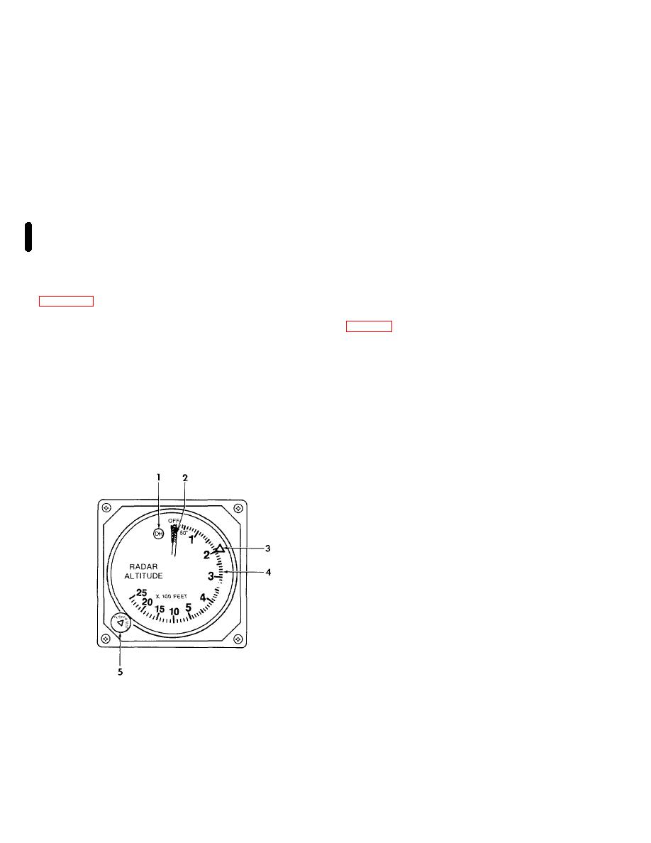
when the aircraft is at or below the selected decision
height.
b. Controls and Functions.
(2) Altitude pointer.
The altitude pointer will
(1) Turn rate indicator. Indicates direction
point to the existing altitude.
and rate of turn. A two minute turn rate is indicated
when the turn rate indicator is deflected one needle
(3) Decision height bug. The decision height
width to the left or right of the index.
bug is set to the desired decision height, by the decision
height set knob.
(2) Index. A reference mark for alignment of
the turn rate indicator.
(4) Altitude scale. The altitude scale is shown
in one hundred feet increments, from 0 to 2500 feet
(3) Inclinometer.
Indicates
lateral
AGL.
acceleration (slip skid) of aircraft.
(5) Decision height set knob . The decision
3-22. Radar Altimeter Indicator.
height set knob is used to set the decision height bug.
a. Description. The KI 250 radar altimeter indicator
3-23. Altitude Select Controller.
2500 feet above ground level (AGL) to touchdown. The
a. Description.
The altitude select controller
indicator is protected by a 1-ampere circuit breaker,
placarded RADAR ALT, located on the copilot's circuit
the desired altitude reference for altitude alerting and
breaker panel.
altitude capture. It is protected through a 1-ampere
circuit breaker, placarded ALT ALERT, located on the
b. Controls and Functions.
copilot's circuit breaker panel.
(1) Decision height (DH) annunciator.
The
decision height (DH) annunciator will illuminate
1.
Decision height annunciator
2.
Altitude pointer
3.
Decision height bug
4.
Altitude scale
5.
Decision height set knob
AP011851
Figure 3-12. Radar Altimeter Indicator
3-20 Change 7
