
TM 55-1510-215-10
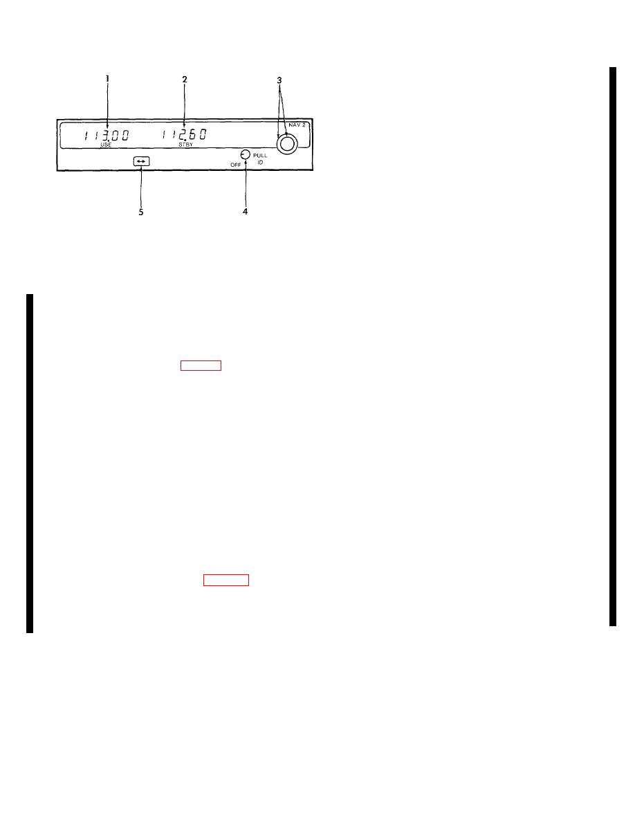
1.
USE frequency display
2.
STBY frequency display
3.
Frequency selector knobs
4.
OFF PULL ID knob
5.
Frequency transfer button
AP011848
Figure 3-15. NAV 2 Receiver
With the ADF button depressed. the unit is placed
the total flight time, while the independent programmable
into the ADF mode and the loop antenna is enabled.
elapsed timer can be reset to count up from zero or be
The ADF message on the left side of the window display
preset to a value and count down to zero. The system is
will display and the indicator needle as selected on the
protected by a 1-ampere circuit breaker, placarded ADF,
RMI's will point to the relative bearing of the selected
located on the right subpanel. The antenna located on
station. In order to tell if there is a sufficient signal for
the lower side of the aircraft (fig. 2-1). contains both
navigational purposes, place the unit back in the ANT
loop and sense antennas, preamplifiers, and modulators,
mode, parking the indicator needle as selected on the
which combine the antenna signals into a single RF
RMI's at 90-degrees. When the unit is then switched to
signal which is output to the receiver via a triaxial cable.
the ADF mode, the needle should slew to the station
b. Operating Modes. The automatic directional
bearing in a positive manner.
without excessive
sluggishness, wavering, or reversals.
finder (ADF) has two operational modes. In the ANT
(antenna) mode, the loop antenna is disabled. and the
c. Controls and Functions.
unit acts as a receiver, allowing audio reception through
the speaker or headphones. The indicator needle as
(1) Mode display.
Displays operating mode
selected on the RMI's will park at a 90-degree relative
the unit is in.
position and the ANT message on the left side of the
display window will display. This mode will provide a
(2) USE display.
Displays frequency which
slightly clearer audio reception, and is used for station
the system is tuned to.
identification. In various parts of the world, some L/LM
stations use an interrupted carrier for identification
(3) FRQ display. Illuminates when a standby
purposes. A beat frequency oscillator (BFO) function is
frequency has been inserted for display.
provided to permit these stations to be more easily
identified. Pushing the BFO switch (fig. 3-16) will cause
(4) STBY/TIMER display. Displays standby
a 1000 Hz tone to be heard whenever there is a radio
frequency, flight time or elapsed time.
carrier signal present at the selected frequency. It will
also light the BFO message in the center of the display.
Change 5 3-25
